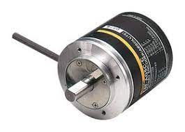
A rotary encoder is an electromechanical device used to monitor rotating objects like shafts and axles. Rotary encoders can be used to measure the position, distance and angular velocity of the rotating shaft.
There are two types of rotary encoders: incremental rotary encoders and absolute rotary encoders. In this article, we’ll be looking at absolute rotary encoders, their working principle and applications.
What is an Absolute Rotary Encoder?
Absolute rotary encoders belong to the family of rotary encoders. They are used to measure following parameters of rotating objects like shafts or axles:
- Angular velocity
- Position information
- Distance
Absolute rotary encoders are found in applications where the precise measurement of position and angular displacement is required. These sensors also find their applications in systems where rotational speed should be measured.
These sensors output a unique word (a word is a set of bits) according to the current position of the sensor.
This is different from incremental rotary encoders as incremental encoders are designed to output a continuous stream of ubiquitous pulses while absolute encoders output a unique set of bits per each position of the sensor.
This allows us to measure the exact(absolute) position of the shaft rather than calculating the change in position.
Let’s have an in-depth look at how absolute rotary encoders work.
Absolute Rotary Encoder Working Principle
Absolute rotary encoders, when compared with incremental rotary encoders, are somewhat complex in operation, but simple to use in an application.
Similar to the incremental rotary encoders, absolute encoders also have a rotating shaft attached to the sensor. The shaft is connected to a disk with a carefully placed set of slots. This wheel is also known as the ‘codewheel’.
The codewheel has a unique bit pattern. Unlike incremental encoders where all the slots are placed in a repeating pattern, absolute encoder codewheel’s slots are different from each other.
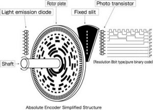
When the shaft rotates, the codewheel also rotates along with it. There are a set of LEDs that emit beams of light onto the codewheel. When the light beams align with the slots, the beams pass through the codewheel, the fixed slit and illuminate the phototransistors.
There are magnetic absolute encoders that replace the LED array with a magnetic sensing array and a set of magnetic poles replacing the optical markers.
Each phototransistor works independently and when illuminated, they output a logic HIGH signal. When there is no beam present at a particular phototransistor, it outputs logic LOW.
The number of phototransistors and levels of slots engraved in the codewheel determines the accuracy and resolution of the absolute rotary encoder.
This is usually stated in bits. For example, an 8-bit resolution absolute encoder can provide 256 position information, and can measure angular displacements of 1.41 degree increments.
Depending on the type of the absolute encoder and its construction, there are multiple output configurations available:
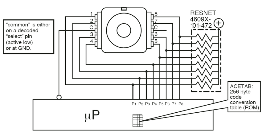
- Parallel output
- This type of sensor has multiple output lines that provide the position information. For example, an 8-bit parallel output sensor has 8 signal lines and two power supply wires. The output can be encoded in binary or gray code format.
- Parallel output sensors have a very minimal amount of built-in circuitry as it does not involve a lot of processing.
- Serial output
- Serial output absolute encoders output the position and speed information through a synchronous data transmission protocol.
- Serial output sensors have data and clock lines, and output one bit per every clock pulse. These sensors also come in either binary or gray coded output formats.
- For added noise immunity, serial output type sensors use differential pair communication as per RS-422 standard. One pair per clock and another for the data lines.
- Most popular synchronous communication methods for absolute encoders are SSI: Synchronous Serial Interface, BiSS: Bidirectional Synchronous Serial Interface and Hiperface DSL. There are also proprietary interfaces such as EnDat2.2.
- Analog output
- Analog output sensors output a voltage or a current value depending on the position of the sensor.
Advantages of Absolute Encoders
Absolute encoders, although cost a bit higher have multiple advantages in terms of position sensing:
- Outputs the absolute position of the shaft
- When ‘polled’, absolute encoders output a unique position information related to its current position. This means that no two positions of the shaft in a 360 degree rotation are identical.
- Multiple output options
- Absolute encoders have multiple output types: parallel, serial (standard and proprietary protocols)
- Immune to power failures
- Absolute encoders do not suffer from power failures. They are always ready to provide positioning information right after a power cycle.
- High resolution
- By simply increasing the number of encoder tracks and sensing units, absolute encoders can have much higher resolution than incremental encoders.
Incremental vs. Absolute Encoders
The main difference between the absolute and incremental encoders is their operation. Absolute encoders can provide position information even when the shaft is not rotating.
Incremental encoders can only provide pulses when the shaft is rotating. A separate pulse count should be carried out to determine the relative position and distance.
Incremental encoders must have a separate ‘homing’ marker to determine the initial/reference position of the shaft. However, absolute encoders do not need such addition and can provide an immediate position to home the shaft.
This can be very useful in applications where rotating the shaft to obtain the ‘home’ position is undesirable.
Incremental encoders require special high-speed decoder modules to obtain the speed, position and distance information. This limits the integration with electronic devices other than PLCs and microcontrollers. Sometimes the processing overhead can negatively affect the system’s performance as well.
Absolute sensors have a higher overall resolution than incremental counterparts. The resolution of incremental encoders is limited to the physical size of the disc and the frequency response of the system.
Absolute encoders are always ready to provide position information on-demand, while incremental encoders need to be constantly monitored to obtain the pulse train and calculate the current speed, direction and distance. Due to this, absolute encoders can recover from power failures easily.
Absolute Encoder Applications
Absolute encoders are mainly used in high-precision positioning applications like,
- Multi-axis CNC machines (assembly and manufacturing)
- Robot arms (surgical robots, diagnostic imaging)
- Positioning system of elevators
- Printing applications
- Motorsport industry (steer-by-wire systems) and many more.
Absolute Encoder Output
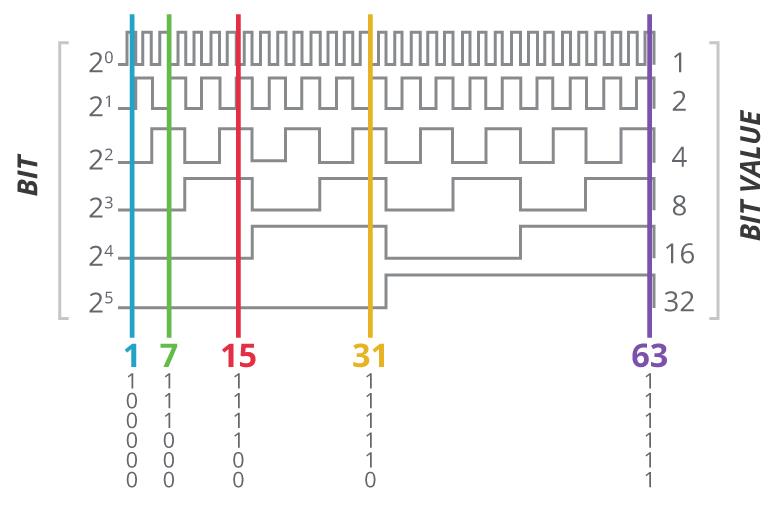
Absolute encoders output a set of bits called ‘a word’ for each position of the shaft. There are three types of outputs for absolute encoders: parallel, serial and analog.
Parallel output encoders have n-number of wires (n=number of bits (resolution)) outputting the corresponding bits of the word. The figure shown below shows a 6-bit word absolute encoder output. The output word can be of grey-code or binary format.
Serial output encoders output a stream of data when ‘polled’. The sensor has a microcontroller based signal processing circuit built-in. There are serial bus systems such as SSI, BiSS, EnDat, Modbus and Profibus that allow a supported device to communicate with the sensor.
Analog output sensors output a voltage or a current signal depending on the position of the sensor.
Types of Absolute Encoders
Absolute encoders can be categorized based on the sensing technology as optical and magnetic. Optical encoders use visible light (LEDs) and a slotted codewheel.
Magnetic encoders use magnetic poles and a magnetic sensing array to obtain the current position of the codewheel.
The other classification is based on the output type. There are single-turn and multi-turn absolute encoders. Single-turn absolute encoders can only provide positioning information in a single 260 degree turn.
Multi-turn encoders provide additional data that provides the number of 360 degree turns the shaft has rotated. This helps to determine the number of rotations without having to count since the beginning.
Single-turn vs. Multi-turn Absolute Encoders
Depending on the availability of a special function to count the revolutions, there are two types of absolute encoders: Single-turn and Multi-turn absolute encoders.
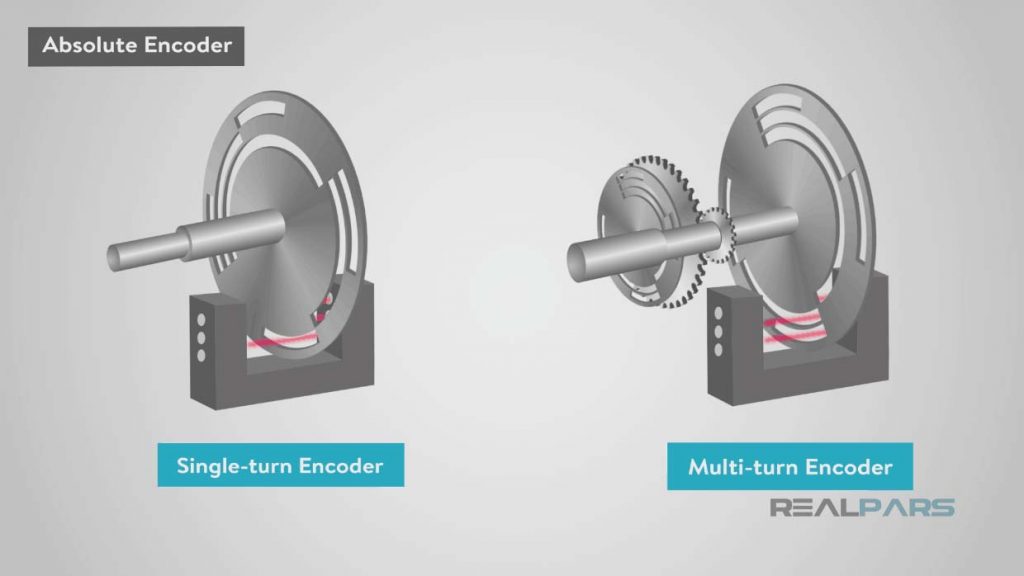
Single-turn absolute encoders can measure the position within one rotation.
For example, if a single-turn absolute encoder rotates 360 degrees from its initial position, and reaches the 361st degree of rotation, the sensor will start the output from the beginning. It will indicate the position as 1 degree.
These sensors cannot count or provide a special signal when the rotation exceeds a full revolution. For example, the 845G series sensors by Allen Bradley have 12-bit output, 0 as minimum and 4095 being the maximum position. Once it reaches 4096, the output reaches 0.
Single turn absolute encoders are found in applications like:
- Telescopes
- Rotating Antennas
- Wind Turbine Generators
- Gates/Doors
Single turn encoders only lack the revolution counting feature and can be used for speed and position measurements. If needed, the initial position can be used as a reference and the software method can be used to count the approximate number of revolutions.
Multi-turn absolute encoders on the other hand, can count the revolutions as well. For example, a 12-bit multi-turn absolute encoder has 4096 steps per revolution, and also can count 4096 revolutions. Multi-turn encoders use one of the following technologies to retain the revolution count:
- Geared type
- Geared encoders use a set of planetary gears to track the number of revolutions. These types have a disadvantage of mechanical wear over time.
- Battery back-up type
- This type uses an electronic counter and a memory to store the counter information. They can count revolutions even when powered off. However, in most cases the battery is built-in to the sensor. It may be required to replace it from time to time depending on the frequency of usage.
- Wiegand sensor type
- Wiegand-wire type sensors use a special wire wound near the shaft and use a magnetic pulse to trigger a change in polarity. This change occurs after each completed revolution. This switching is used to count the number of revolutions.
Multi-turn encoders are found in applications such as,
- Robotic joints
- Cranes
- Servo Motors (360 servos)
- Satellite dish control systems and many more where a rotation pivot point is not accessible/available.
What is a Magnetic Absolute Encoder?
Magnetic absolute encoders use magnetic poles and magnetic sensors instead of LEDs and photodiodes found in optical encoders. The image below shows an example of an absolute-coded magnetic encoder wheel.

The outer pole arrangement has one more magnetic pole than the inner arrangement. This causes the inner and outer pole pairs to be uniquely offset.
The sensors pick up signals from one pole per wheel at a time, and calculate their phase difference (phase shift). This analog phase difference is then converted to a digital value to be output.
Magnetic encoders are very robust and resistant to shock and vibration.
They find their applications in environments where there are particulate pollutants like dust, moisture and other material particles can accumulate. However, due to their operating principle, magnetic encoders are susceptible to disruptions caused by strong magnetic fields.
Interfacing an Absolute Encoder with Raspberry Pi
While connecting an absolute encoder with a Raspberry Pi can be simple, the program to properly read the inputs can become a bit complicated depending on the sensor type. Let’s have a look at how to interface a serial output type absolute encoder (EMS22A) with a Raspberry Pi.
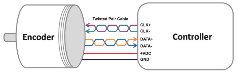
Wiring the sensor
The sensor has the following wiring format:
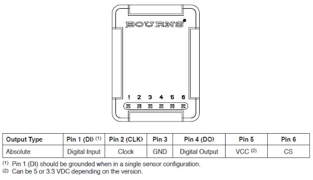
Connect the sensor’s wires as follows with the Raspberry Pi:
- Pin 2 (CLK) -> RPi pin 2
- Pin 4 (DO) -> RPi pin 3 (if using more than one sensor, connect the second sensor’s data pin to pin 14)
- Pin 6 (CS) -> RPi pin 4
- VCC -> RPi +5V pin
- GND -> RPi GND pin
Example Code
To poll the information from the sensor, the following sample code written by HareshKarnan can be used. It will print the reading(s) from the attached sensor when executed.
import time

import RPi.GPIO as GPIO


GPIO.setmode(GPIO.BCM)


PIN_CLK = 2

PIN_DAT = [3,14]

PIN_CS  = 4

delay = 0.0000005

ns = 2 # number of sensors attached

# totally 10 bits to be extracted from SSI signal

bitcount = 16


# pin setup done here

try:

 GPIO.setup(PIN_CLK,GPIO.OUT)

 GPIO.setup(PIN_DAT[:],GPIO.IN)

 GPIO.setup(PIN_CS,GPIO.OUT)

 GPIO.output(PIN_CS,1)

 GPIO.output(PIN_CLK,1)

except:

 print "ERROR. Unable to setup the configuration requested"


#wait some time to start

time.sleep(0.5)


print "GPIO configuration enabled"


def clockup():

 GPIO.output(PIN_CLK,1)

def clockdown():

 GPIO.output(PIN_CLK,0)

def MSB():

 # Most Significant Bit

 clockdown()


def readpos():

 GPIO.output(PIN_CS,0)

 time.sleep(delay*2)

 MSB()

 data = [0]*ns


 for i in range(0,bitcount):

     if i<10:

         #print i

         clockup()

         for j in range(0,ns):

             data[j]<<=1

             data[j]|=GPIO.input(PIN_DAT[j])

         clockdown()

     else:

         for k in range(0,6):

             clockup()

             clockdown()

 GPIO.output(PIN_CS,1)

 return data


try:

 while(1):

     print readpos()

     time.sleep(0.001)

     #break


finally:

 print "cleaning up GPIO"

 GPIO.cleanup()
Absolute Encoder Price
Absolute rotary encoder prices vary from $10-15 to over $1000. This is mainly due to the available features, resolution, output type and the protocol being used. Proprietary, high resolution sensors tend to cost more than simple, parallel output type sensors which can be purchased at a lower cost.
Conclusion
Rotary encoders are used to keep track of rotating mechanical components like shafts and rods. Absolute encoders and incremental encoders are the two types of rotary encoders.
There are special encoder interface devices that can read a rotary encoder’s raw input and output the speed, position and distance information to a computer.
Supported encoders can also be directly connected to PLCs and other computers to obtain the raw values and perform calculations within the software.

