Introduction
There are many types of proximity sensors used in different applications. We use capacitive proximity sensors to detect any type of object without any contact. They sense objects by measuring the change in an electrical property, capacitance.
This article aims to provide a detailed guide on capacitive proximity sensors and their applications.
What is a Capacitive Proximity Sensor?
A capacitive proximity sensor is a sensor that can detect an object using the electrical property, capacitance. They are widely used to detect and measure objects/fluids that have a higher dielectric constant than air. This includes anything that is conductive or non-conductive.
Capacitive proximity sensors have many applications in industrial automation systems from detecting positions to analyzing the composition of objects in a non-invasive manner.
Capacitive Proximity Sensor and How it Works
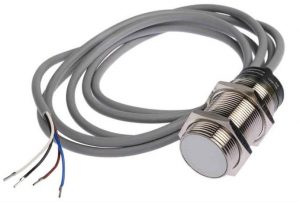
Capacitive proximity sensors are a special application of capacitive sensors. We use them to detect the presence of objects in industrial environments. The image shown below is an RS PRO M30 x 1.5 Capacitive Proximity Sensor.
Before diving into greater detail, let’s understand what a capacitor is and how it works. In simple terms, a capacitor is a device that can hold an electric charge like a battery. They are made of two conductive plates with a dielectric material filling the gap. Depending on the dielectric width, their capacitance (capacity to store electric charge) changes.
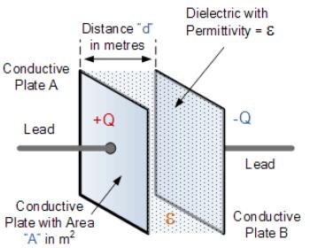
The dielectric constant depends on the material. Materials with a high dielectric constant are easy to detect. For example, water is more detectable than oil or PVC. This is because water has a dielectric constant of about 78 and for PVC it’s only about 5.
A capacitive proximity sensor follows the same principle, only one of the plates is now the object we want to detect. Bringing an object close to the sensing face causes the capacitance to change. The sensor can then measure the change and determine if the object is close.
It is not possible to directly measure the change in capacitance by ordinary means. To address this, capacitive proximity sensors have specialized circuitry inside them. The circuit does all the signal processing to ultimately output a usable, digital signal.
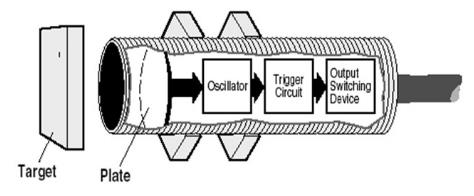
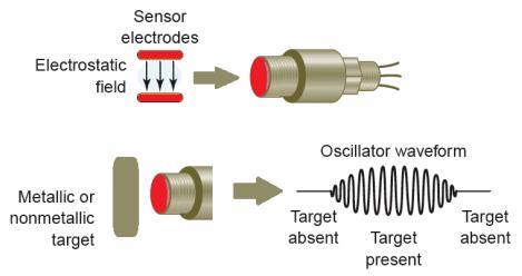
The first stage of the sensor is the capacitor itself. When an object is near the sensing face, it forms a capacitor. The air between them becomes the dielectric material. Inside the sensor, there is an oscillator circuit. This can either be an RC or LC oscillator circuit.
The capacitance created by the external object starts an oscillation in the circuit. This smallest distance an object has to maintain with the sensor face to start the oscillation is also known as the ‘operating point’. This is adjustable in most of the sensors. When an object comes closer to the sensor, this oscillation frequency increases. This causes the amplitude of the oscillation to increase.
The circuit also consists of a trigger circuit with hysteresis. The trigger circuit monitors the frequency and the amplitude of the oscillation. It controls the output if the amplitude goes beyond a pre-set value. There are sensors that can output digital or analog signals.
Proximity sensors provide means to adjust their operating point of. Some have potentiometers while others may have a dedicated ‘teach button’. This button or the potentiometer screw can be used to calibrate the sensor. Increasing the sensitivity also makes the sensor more susceptible to false detections. This means that sometimes even changes in humidity and temperature can cause the sensor to trigger.
Capacitive sensors can detect both conductive and non-conductive material. Conductive materials are the easiest to detect as they form a good capacitor with the sensor. In this case, the dielectric strength becomes negligible.
Detecting non-conductive material depends on three factors:
- Size of the sensor surface – larger surface allows longer sensing distances
- The dielectric constant of the target material – higher the constant, longer the distance
- The surface area of the target – larger surface area, longer distance
Target speed and temperature can also affect the sensing distance.
Sensing Range
A capacitive proximity sensor has a larger sensing range than its inductive counterpart. The detection range falls between 3 to 60mm. The largest sensing distance is based on a standard target, a 1mm thick Fe 360 grounded steel plate. This should have a side length that is the diameter of the sensor surface. If the sensing distance is greater than the diameter, the side length should be three times the rated sensing distance.
Non-conductive objects should have a reduction factor based on the material’s dielectric constant. There are tables that provide approximate values for some materials. They help to determine an accurate sensing distance.
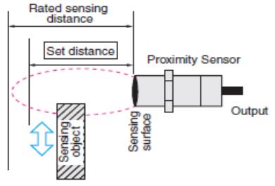
There are two important parameters when considering the sensing range:
- Rated/nominal sensing distance (Sn)
- This is a theoretical value. It does not include manufacturing tolerances, operating voltages, or temperatures.
- Effective sensing distance (Sr)
- Defined for a specific set of conditions. (i.e. flush mount, room temperature, and a given supply voltage)
Hysteresis
Hysteresis is the difference between the switch on distance and the switch off distance. It defines a zone rather than a line for sensing an object.
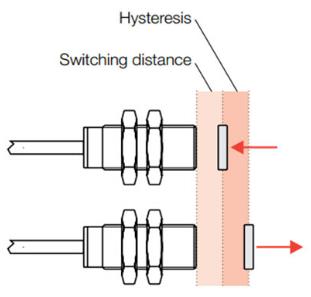
Hysteresis causes the output to ‘latch’ even when the object moves from or towards the sensor’s field. This prevents the ‘chattering’ effect (switching the output on and off over and over) if an object is at the edge of the detection range.
Hysteresis is an independent parameter. It is a percentage of the rated sensing distance. For example, a sensor with 20mm rated sensing distance can have a max hysteresis of 15%. This is about 3mm of the sensing range. It can vary from sensor to sensor, even between the same model.
There are multiple factors that can affect hysteresis:
- Ambient and local sensor temperature
- Atmospheric pressure
- Relative humidity
- Mechanical stress of sensor housing
- Sensitivity correlation – higher sensitivity, larger hysteresis
Capacitive Sensor Types
Capacitive sensors are used to detect many types of materials. This also includes fluid flow, liquid level, and even pressure. There are a variety of capacitive proximity sensors on the market:
- Miniature capacitive sensors
- Miniature capacitive sensors come in cylindrical or wafer-type packages to save mounting space. These sensors do not have the signal processing circuit inside them. A separate amplifier is used to process the signals.
- Cylindrical capacitive sensors
- These are larger than miniature sensors and can have a diameter from 6.5mm to 30mm. Their sensing distances are adjustable.
- High temperature capacitive sensors
- High temperature capacitive sensors are designed to withstand extreme temperatures and can even handle direct contact with high-temperature objects/fluids.
- Analog capacitive sensors
- These find their applications in material selection, thickness monitoring, and concentration checking tasks. Analog sensors output a range of voltages/currents to help determine the type of object it’s monitoring.
Capacitive Sensor Wiring Diagram
There are quite a few sensor wiring diagrams used in the automation industry. We can classify sensors based on their supply voltage type and the output type:
- AC or DC supply
- Determines whether the sensors works with 220V AC or 24V DC power supply
- Output type
- Transistor output (3-wire)
- Transistor output sensors can be either NPN or PNP. For both of those types, here are NO (Normally Open) and NC (Normally Closed) output options. Some sensors may even support both. (NO+NC).
- Relay output (2-wire or 3-wire)
- AC 2-wire and 3-wire sensors are always relay output type. DC sensors can be either relay or transistor output type. Relay output sensors also have NO, NC, and NO+NC options.
- Transistor output (3-wire)
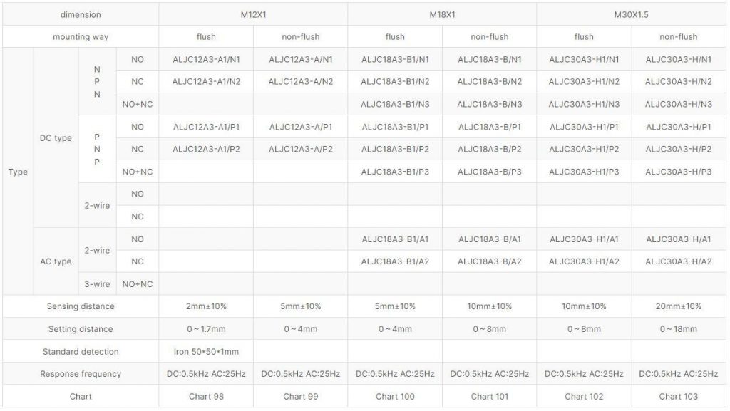
Here is OMCH.co’s range of capacitive proximity sensors and the wiring options they provide:
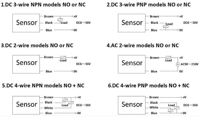
Shown below is the commonly used wiring diagram of a few proximity sensor types. Although not uncommon, 4-wire models are not widely used other than in very special applications.
Sensitivity Adjustments of a Capacitive Sensor
There are two approaches. we can take to adjust the sensitivity of a capacitive sensor.
- Adjusting the sensor position
We can adjust the sensor position by adjusting the thread and the locking nuts. This allows us to place the sensor closer or away from the object and permanently mount the sensor to a bracket. The adjusting should take place when the sensor is powered up and the object to detect is present. Adjust the sensor back and forth until the sensor’s LED indicates that the object is detected.
- Adjusting the sensor’s sensitivity
Sensitivity adjustment of a proximity sensor is useful when we cannot adjust the sensor position.
To adjust a sensor to detect the presence of an object or full condition, follow these steps:
- Rotate the adjustment screw counterclockwise and decrease the sensitivity to a minimum.
- Place the object to be detected within the sensor’s detection range. Slowly turn the adjustment screw clockwise until the sensor detects the object. The LED indicator on the sensor lights up when it detects the object.
- Turn the adjustment screw ¼ turns further for safety (optional step)
To adjust a sensor to detect the absence of an object or empty condition, follow these steps:
- Rotate the adjustment screw clockwise and increase the sensitivity to a maximum.
- The LED indicator on the sensor will light up even when no object is present.
- Turn the adjustment screw counterclockwise until the LED turns off.
- Turn the adjustment screw ¼ turns further for safety (optional step)
Capacitive Proximity Sensor Circuit in Depth
For those who are interested in understanding the working principle of a capacitive proximity sensor, let’s have an in-depth look.
As mentioned before, a capacitive proximity sensor houses complex circuitry inside it. It has four main parts:
- Oscillator Stage
- Demodulator Stage
- Trigger Stage
- Output Stage
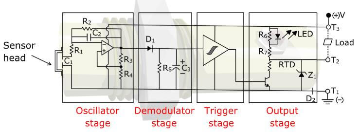
Oscillator Stage
The oscillator stage contains an RC relaxation oscillator. This circuit is an op-amp based circuit. Capacitors and resistors in this circuit determine the frequency of oscillation. The capacitor C1 used to control the oscillation frequency is coupled with the sensor head. If an external object reaches near the sensor head, the oscillation frequency changes. The oscillating signal from this stage is an input to the demodulator stage.
Demodulator Stage
The demodulator stage takes the oscillating signal from the previous stage and rectifies it. This circuit shown above has a half wave rectifier. The capacitor C3 smoothes the voltage signal and outputs a stable, DC voltage into the trigger stage.
Trigger Stage
This stage has a special component named ‘schmitt trigger’. This device can ‘latch’ onto a specific output through a range of inputs. For example, a schmitt trigger may output logic HIGH for input voltages more than 3V, and output logic LOW once the input voltage drops below 2.5V. The 0.5v difference is called ‘hysteresis’ and it helps the output to stay stable if the input voltage slightly changes.
Output Stage
The trigger stage controls the output stage. The sensor shown here has a transistor output. It is a sinking type (NPN) output. Once the trigger stage gives a logic HIGH signal, the transistor in the output stage activates. It causes the load circuit to complete and activates the load. In relay output sensors the transistor is replaced by a small relay.
The output stage also consists of diodes D2 and Z1 to protect the sensor. If the power supply polarity is reversed, these diodes will protect the sensor.
Capacitive Proximity Sensors vs. Inductive Proximity Sensors
Capacitive and inductive proximity sensors are two of the most popular proximity sensors. Capacitive sensors can detect both conductive and non-conductive materials. Inductive proximity sensors can only detect metallic (conductive) material.
Inductive proximity sensors use the principle of electromagnetism to detect objects. Due to this reason, they can only detect metallic objects made of iron, copper, or aluminum. Their internal circuitry is very similar to capacitive sensors. The main difference is in the oscillator circuitry. Inductive sensors use principles of electromagnetism and Eddy currents while capacitive sensors use capacitance to control the oscillation.
Inductive sensors are fairly faster and in the range of 10-20Hz in AC and 500Hz-5kHz in DC. They have a sensing range of about 4-40mm. Specially designed sensors are also available that have sensing distances up to about 80mm. However, they have a narrow sensing range due to magnetic field limitations.
Capacitive sensors are relatively slower than inductive sensors. This is because it involves charging the conductive plate in the sensor. The speed is in the range of 10 to 50Hz. Capacitive proximity sensors have a nominal range of 3mm-60mm. There can be special sensors that have higher sensing distances.
Capacitive sensors are more error-prone as they can detect all types of objects. This can cause false triggering of the sensor by non-target materials. Therefore if the interest is in metallic objects, an inductive proximity sensor can be a better choice. For example, to detect metallic objects in a food product, an inductive proximity sensor is a more reliable option.
Capacitive Proximity Sensor with Arduino
Industrial sensors are built to work with higher voltages such as 12V or 24V DC and even 220V AC. Arduino development boards work with 5V DC. To use a proximity sensor with an Arduino, it is necessary to convert the high voltage signal into a lower voltage.
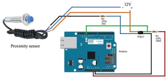
In this circuit by Electroclinic, a PNP-type proximity sensor is used. The PC817 optocoupler/optoisolator protects the Arduino from high voltage signals. Pin 1 of the PC817 connects to +12V, and pin 2 is connected to the sensor’s black wire through a 1k resistor. Sensor is powered using brown and blue wires as usual. (Brown – +12v, Blue – 0V)
To read the sensor, Arduino pin 13 is connected to pin 4 of the optocoupler, and is pulled-up using R3 (10k resistor). This stabilizes the input signal when the sensor is not active.
When no object is detected, the optocoupler remains inactive. Pin 13 of Arduino stays at +5V. When the sensor is active, the optocoupler turns on and pulls the pin 13 to 0V. This is monitored from the code and can be used to make decisions such as turning on/off a motor.
int limitswitch=13;
int state= LOW;
int value;
void setup()
{
Serial.begin(9600);
pinMode(limitswitch,INPUT);
}
void loop()
{
value = digitalRead(limitswitch);
if(value!=state)
{
state=value;
Serial.println(“sensor value =”);
if (state==0)
{
Serial.println(“target detected”);
}
else{
Serial.println(“No target detected”);
}
}
}
Capacitive Proximity Sensor Symbol
3-wire and 2-wire proximity sensors are the most common in the automation industry. To distinguish them, each of them has its own standard symbol defined by IEC (International Electrotechnical Commission).
3-wire proximity sensor symbol
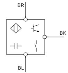
BR wire at the top indicates that the colour is brown (BRown), and it’s the positive wire. BL wire in the bottom denotes its colour as blue (BLue) and indicates it’s the 0V wire. BK is the black (BlacK) wire, which is the output.
The symbol contains 4 sub symbols. Top left symbol indicates that this is a proximity sensor. The transistor symbol indicates if the sensor is NPN or PNP type. Bottom left symbol indicates that it’s a capacitive sensor while the bottom right symbol means the output is normally closed.
2-wire proximity sensor symbol
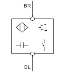
The IEC symbol for the 2-wire proximity sensors is almost identical to its 3-wire counterpart. The only difference is that this symbol does not have a separate output wire.
The symbols within the main component symbol can slightly change depending on the configuration of the sensor. This includes output type, sensing mode (capacitive, inductive etc.) and NO/NC output configuration.
Capacitive Proximity Sensor Application
Capacitive proximity sensors are used in industrial applications to detect both solid objects and liquids. Their industrial applications include:
- Production automation such as counting products, product transfers
- Filling processes (i.e. grain, powder, ink, water, etc.)
- Fluid level sensing
- Composition testing (density, thickness, etc.)
- Pressure sensing
- Moisture sensing
Capacitive proximity sensor price
The price of the capacitive proximity sensors depends on various factors such as size, sensing distance, operating voltage, output type, and additional features like IP (Ingress Protection) ratings and temperature ratings.
Capacitive proximity sensor prices can vary from around $30 up to $1500 for more complex and specialized models.
What can a capacitive proximity sensor detect?
Capacitive proximity sensors can detect both conductive and non-conductive objects. The objects/material can be in solid, granulate, powder, and even liquid form. However, they are mostly used to detect non-metallic materials like wood, grain, plastic, glass, water, and other liquids such as fuel and chemicals.
With added improvements, capacitive proximity sensors can detect even more parameters such as pressure and liquid flow.
What are capacitive proximity sensors made of?
There are a few types of materials used to make capacitive proximity sensors. Cylindrical type proximity sensors are typically made of stainless steel. Sensors with stainless steel housings are more durable and suitable for use in high-temperature/ corrosive environments.
Plastics like PBT(Polybutylene Terephthalate) and PVDF(Polyvinylidene Fluoride) are used to make smaller sized proximity sensors such as rectangular models. They are temperature, flame, and UV resistant and provide extra protection to the sensor circuitry. These specialized plastics find their usages in corrosive chemical applications.
Conclusion
In this article, we discussed capacitive proximity sensors, their construction, principle operation, and applications. While capacitive sensors are versatile, there are other proximity sensor types that may be more suitable for a specific application. Care should be taken to correctly identify the best type of proximity sensor and calibrate them to ensure the measurements taken are correct and accurate.

