Introduction
Relays are found in almost any machine that has an electrical system.
From household appliances like washing machines and refrigerators to industrial applications such as fuel pumps, motor control and many more. Relays are used to control high voltage and high current devices.
In this article, we’ll be taking an in depth look at electromagnetic relays, their operating principle, characteristics and the type of relays that are found in industrial automation applications.
What is an Electromagnetic Relay?
An electromagnetic relay is a switching device that uses a magnet to turn the switch on or off. They belong to the category of electromechanical devices.
Electromechanical devices use physical contacts to switch the outputs. Due to the movements occurring inside the switch, they have a characteristic ‘ticking’ sound during operation.
Relays are used to control a larger electrical load using a small input signal. For example, the input from a small push button can activate a relay and thereby control a large induction motor; where the pushbutton alone is not sufficient to turn on/off the motor directly.
A relay basically consists of a coil and a set of spring-mounted moving contacts. There are multiple types of relays based on their construction and mode of operation. Let’s look at the basic functionality of an electromagnetic relay.
How do Electromagnetic Relays Work?
There are many types of relays. Due to the simplicity of construction, let’s look at the attracted armature type relay and how it functions. The diagram below shows the typical construction of such a relay, which has a single pole double throw (SPDT) configuration.
The primary components of a relay are the solenoid/electromagnet, armature-spring assembly and the contacts. Let’s discuss their individual tasks, and how they work together to act as a switch.
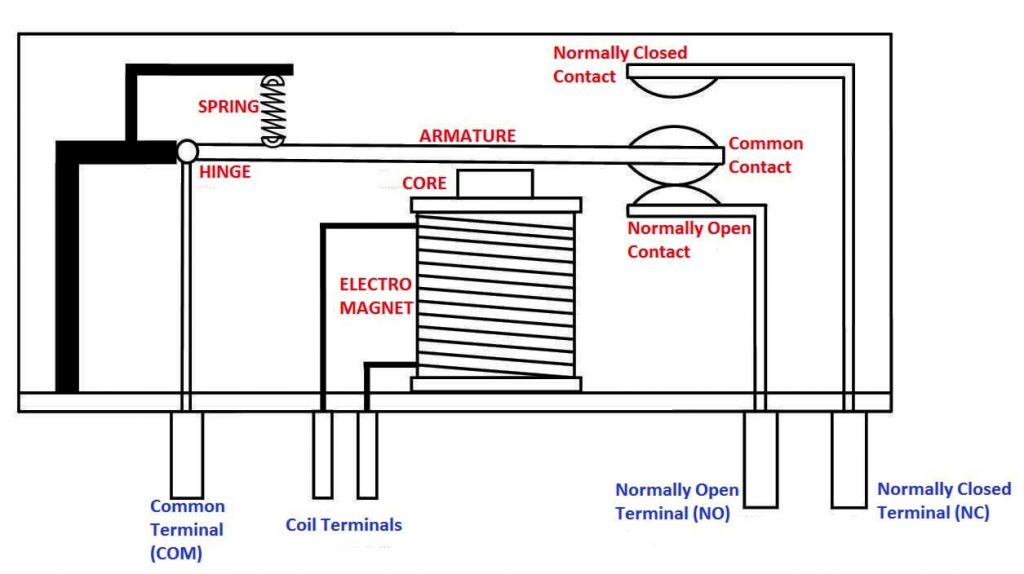
The solenoid (also known as the electromagnet) is a copper coil wound around a ferromagnetic material. This is typically a solid iron core. When a voltage is applied to the coil, a magnetic field is generated around the coil.
The iron core concentrates this magnetic field to become a magnet until the voltage to the coil is removed.
Solenoids are usually operated using DC current, and are not compatible with AC sources. However there are AC operated relays also available.
AC relays have an additional component in the electromagnet named ‘shading ring’. This prevents the electromagnet from demagnetizing whenever the AC supply crosses the zero point. Therefore, the armature can stay attracted to the electromagnet as long as the coil is powered on.
The armature-spring assembly is the moving component that is found in a relay. The armature is positioned such that when the electromagnet is powered on, it can deflect the armature towards it.
There is a return spring in place to ensure that the armature returns to its initial position when the coil is not powered on. The armature is conductive as it should carry the switching current from the common terminal to the output terminals.
The contacts are the next most important and most abused parts in a relay. When switching a load, the armature moves the contacts between the stationary contacts. This causes sparks to generate. If the switched load is a highly inductive load such as a motor, sometimes arcs can also be seen.
Therefore, the contact material is selected to withstand the electrical corrosion. Usually, they are made of silver nickel, silver cadmium oxide and silver tin oxide.
Once the coil is energized, the electromagnet activates. This causes the armature to be attracted towards the electromagnet, which in turn makes the connection between the common contact and the normally open contact.
At the same time, the connection between normally closed contact and the common contact is severed.
There are several types of electromagnetic relays available. Some of them are used to control heavy loads while others are used primarily as protection devices.
Electromagnetic Relay Types
- Attracted Armature type relay
- Attracted armature type relay is the simplest type of electromagnetic relays. There are two types of attracted armature relays: hinged armature and plunger type. Hinged armature type is the most common one.
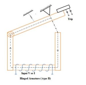
- When the coil is energized, the contacts are broken/closed depending on the normally open/close mode of output.
- Attracted armature type relays are normally DC operated and once activated, the contacts do not return to their initial position. They need to be reset manually.
- Attracted armature type electromagnetic relays are found in safety devices as over current, overvoltage and undervoltage protection relays, and are sometimes used as auxiliary relays as well.
- Induction Disc type relay
- Following the principle of electromagnetic induction and Ferrari’s principle, induction disc type relays are mainly used as protective relays in AC systems.
- When energized, the disc inside the relay starts to rotate. The moving contact also rotates with the disk and can come into contact with the field contact, completing the circuit. De-energizing the relay causes the spring to rotate the disc in the opposite direction and return to the initial point.
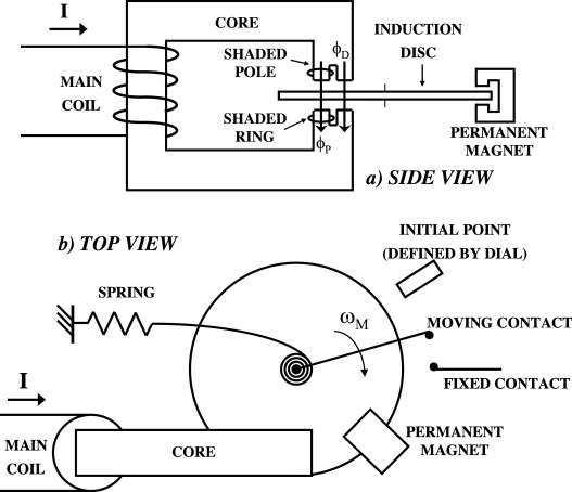
- Induction disc type relay is specially designed to work with AC systems and do not work with continuous DC supplies.
- Induction Cup type relay
- Induction cup type relays are similar to the induction disc type relays. The main difference is that in the induction cup type, the rotating disc in the disc type relay is replaced with a C-shaped aluminium cup. This reduces the disc inertia and allows faster operation.
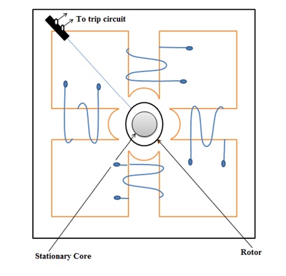
- Induction cup type relays are used in high speed applications such as directional or phase comparison applications. This is possible due to their high sensitivity, vibration stability and lower inertia.
- There are two main types of induction cup type relays: reactance or Mho type relays (for measuring reactance in circuits), directional or power relay (provide maximum torque to trigger contacts at fault conditions).
- Balanced Beam type relay
- Balanced beam type electromagnetic relays are also a type of attracted armature relay. They have a hinge placed in the middle of the armature rather than at an end. The two ends have independant electromagnets, one proving the holding/retaining torque(left) and the other providing the operating torque(right).
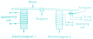
- During normal operation, the attraction force generated by the retaining electromagnet is sufficient that the armature stays attracted to it. At his point, the operating coil’s field is cancelled out by it. At a fault condition where operating current is high, the attraction force from the operating electromagnet becomes greater than the retaining electromagnet. This forces the beam to deflect and makes contact with the contacts of the trip circuit.
- These relays are generally faster, however any DC transients (spikes) can also trigger them. Therefore these relays are not used commonly.
- Moving coil type relay
- Among the family of electromagnetic relays, moving coil type relays are the most sensitive. They are used in distance and differential protection applications because of their high sensitivity, and work only with DC systems. For AC systems, they can be retrofitted using additional rectifier circuits.
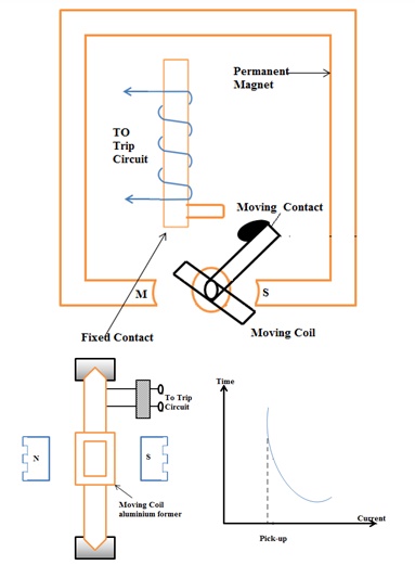
- In this type of relay, the moving coil can be of type axial or rotary. Axial type has twice the sensitivity than the rotary type. The coil is wound around the moving part (spindle) as shown in the above figure. Applying current through the coil causes it to rotate due to the repulsion caused by the poles in the permanent magnet. The rotation causes the moving contact to close the trip circuit contacts.
- Polarized Moving Iron type relay
- Polarized type relays, as the name suggests, have a polarized coil. This implies that the relay will only work with a certain polarity of voltage applied to the coil. This type of relays are specially found in high sensitive applications where the systems operate on DC supplies.
- The construction of these relays are similar to the moving coil type relays, but polarizing relays also contain permanent magnets in them to introduce the polarity to the coil.
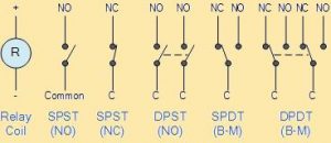
Electromagnetic Relay Symbol
Electromagnetic relays are represented in numerous ways in electrical diagrams. Some contain generic symbols and some diagrams can have complex symbols, indicating the actuation type and number of poles/outputs of the relays. Let’s have a look at some of the most common relay symbols found in electrical drawings.
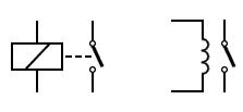
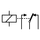
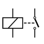
- Relay – Solenoid Operated – SPST
- This relay has only one make or break contact. The left portion represents the coil while the right part represents the two contacts of the switch. Sometimes the coil is represented as shown in the right image. SPST relays have 4 pins.
- Relay – SPDT – Single Pole Double Throw
- This relay is similar to the SPST model, but has two outputs. While not active, the COM input is connected with the NC output. When energized, the relay breaks the contact with the NC and closes the contact with NO output. It has 5 pins in total.
- Relay – DPST – Double Pole Single Throw
- This relay has two, isolated switches that can be used for two different tasks. It has 6 pins including the 2 pins for the coil.
Depending on the pin count, number of poles/throws and technology, there are numerous other standard symbols being used in electrical drawings. Electrical-symbols has a comprehensive guide on these symbols on their website.
Electromagnetic Relay Applications
Electromagnetic relays are used where large electrical loads need to be switched using a small signal. Relays are also used to provide electrical isolation between high voltage and low voltage systems to provide protection to low voltage systems and the users.
Relays find their applications in,
- Automobiles
- Fuel pump, horns, starter motors, windshield vipers
- Building automation
- Access control systems, elevators, control panels
- Industrial automation
- Motor controllers, light controllers, power supply distribution and switching
- Domestic electric appliances
- Ovens, washing machines, indoor/outdoor AC units
And many more.
How long does an Electromagnetic Relay Last?
Since relays contain moving parts and are subjected to constant connection/disconnection, they have a relatively lower life expectancy than their solid-state counterparts.
Typically, the first part of a relay to fail is the contacts. According to FDA, relays have a life expectancy of 100,000 operations for their contacts and 10 million operations overall.
However, if the relays are constantly under heavy load, their life expectancy could be much lower. For instance, if a relay is used to switch loads much higher than its rated value, the contacts may degrade faster and can ultimately fuse together, creating a hazardous situation.
How to Test an Electromagnetic Relay
Electromagnetic relays can be tested by either using a load or multimeter. The procedure to check a relay using the multimeter is as follows:
- Set the multimeter mode to continuity/buzzer mode. Connect the probes to the coil terminals of the relay. If the buzzer rings, the coil is OK and functional.
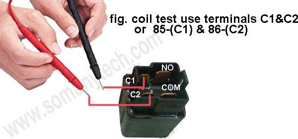
Testing the coil can also be done using the resistance measuring mode. A functional coil will have a resistance around 10-500 Ohms.
- Connect the probes to NO and COM terminals. At this point, the buzzer should not ring. If the buzzer rings, the relay is faulty.
- Similarly, connect the probes to NC and COM terminals. The buzzer should now ring (if the meter is in resistance mode, it should indicate 0 Ohms.). If it does not, it implies that the relay is faulty.
How Many Pins Does an Electromagnetic Relay Have?
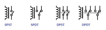
Electromagnetic relays are available in all different shapes and sizes. Depending on their configuration, relays can have a pin count from 4, 5, 8 and sometimes even more. There are a few configurations of relays that are widely available:
- SPST – Single Pole Single Throw
- SPDT – Single Pole Double Throw
- DPST – Double Pole Single Throw
- DPDT – Double Pole Double Throw
In addition to the contact terminals, there are two additional terminals that are connected to the coil.
Conclusion
Electromagnetic relays are one of the most common types of switching elements found in automation systems. They are used to control high voltage and high current loads using lower voltage signals.
Relays are used as both switches and safety devices. As an alternative, there are solid state relays that can replace electro-mechanical relays, which are more robust and durable.

