Introduction
Industrial automation applications often need detection of objects. There are many types of sensors that are designed to detect the presence of objects made of almost any material.
Hall effect sensors are specially designed to detect magnetic objects. They are often found in speed/position measuring applications.
What is a Hall effect proximity Sensor?
Hall effect sensors belong to the family of proximity sensors. They detect the presence using the magnitude of the magnetic field created by an object. The principle of Hall effect is used to detect the presence and intensity of a magnetic field.
Hall effect sensors can detect any magnetic object that has the correct polarity and sufficient strength. This includes electromagnets and permanent magnets like neodymium magnets.
Hall sensors are used in position, proximity, and speed sensing applications. For example, the modern day automobiles use hall effect sensors to calculate the vehicle speed, engine crankshaft position, and speed.
One of the most popular systems that use hall effect sensors is the Anti-lock Brake (ABS) systems in vehicles. In automation applications, hall sensors find their usages in motor control and even DC current sensing.
How does a Hall effect proximity sensor work?
Hall effect sensors primarily consist of a thin piece of rectangular semiconductor. The semiconductor is often made of gallium arsenide (GaAs), indium arsenide (InAs), or indium antimonide (InSb).
A continuous current is allowed to pass through this conductor at all times. When a magnet is placed close to this thin semiconductor, it disrupts the current flow by deflecting the charge carriers in the semiconductor.
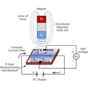
This phenomenon causes a voltage difference to build up, perpendicular to the flow of current and across the semiconductor. This is shown in the picture above as positive and negative charges.
This voltage is called Hall voltage, named after the physicist Edwin Herbert Hall who discovered it. To generate a measurable voltage difference, the magnet must be:
- Magnetic flux lines should be perpendicular
- The pole towards the sensor should have the correct polarity. This is often the south pole of the magnet.
A typical Hall effect sensor have the following block diagram which represents its circuit’s functionality.
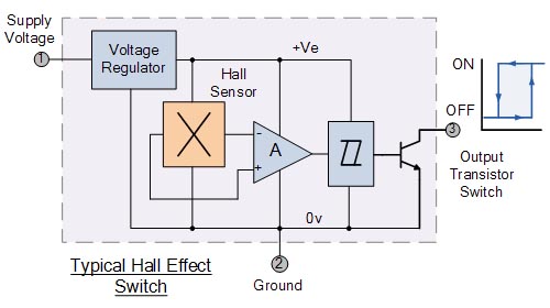
The voltage regulator provides a smooth, stable voltage for the sensor, the amplifier, and other components.
When a magnetic object is placed near the sensor, the Hall voltage increases. The amplifier amplifies this difference to feed the schmitt trigger to provide a clean, jitter-free output.
When the amplified signal exceeds a certain threshold, the schmitt trigger is activated. The signal from the schmitt trigger activates the transistor.
The transistor works as the output switching device, which turns the output on or off. The output stage component depends on the sensor’s output type.
It can be a transistor (NPN/PNP), a relay, or even the raw, analog signal which represents the magnetic field’s strength.
What are the types of Hall effect sensors?
Hall effect sensors can be categorized in multiple ways.
- Bi-polar and Uni-polar Hall effect sensors
- Bi-polar sensors are also known as ‘latching’ types. Their outputs are activated when a positive magnetic field (south pole) is present. To switch off/release the output, a negative field (north pole) should be applied.
- Uni-polar sensors switch on the output when a magnetic south pole is present, and turn off its output when the magnet is removed.
- Digital and Analog Outputs
- Digital output type sensors output a distinct logic HIGH or LOW output while analog sensors output a range of values like 0-5V or 4-20mA.
What is the range of a Hall effect sensor?
Hall sensors have a typical operating range of about 0-40mm. However, this is also directly dependent on the magnetic flux density of the object.
Stronger magnets have more influence and can trigger the sensor at a relatively higher distance. Weaker magnets should be placed very close to the sensor to trigger it.
What is the difference between a Hall sensor and an Inductive sensor?
The main difference between these two sensors is the way they detect objects. Inductive proximity sensors generate their own magnetic field and monitor the field’s change to detect objects.
This means that the sensor monitors the change in its own magnetic field by external objects.
Hall effect sensors monitor external magnetic fields. They require the object being detected to create its own magnetic field. Therefore hall effect sensors can only detect permanent magnets and electromagnets.
Inductive proximity sensors can detect many types of metals like iron, copper, and aluminium.
Hall effect proximity sensors are susceptible to magnetic interference. Inductive proximity sensors are relatively tolerant to these interferences. However, the performance of both sensors can be affected by extreme temperatures and chip buildup.
When considering the installation complexity, inductive sensors are relatively easier to install because they can use part of the machine as a sensing object (i.e. limit sensing).
Hall sensors require a special magnetic attachment to be attached to the machine other than the sensor itself (i.e wheel speed sensing).
How to Use a Hall Effect Sensor With Arduino
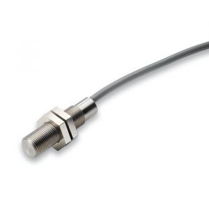
Similar to industrial proximity sensors, there are miniature versions of them available in the market. The US5881/US1881 are some of the popular hall effect sensors that are 5V compatible.
This means that we can easily integrate them with an Arduino to sense magnetic objects.
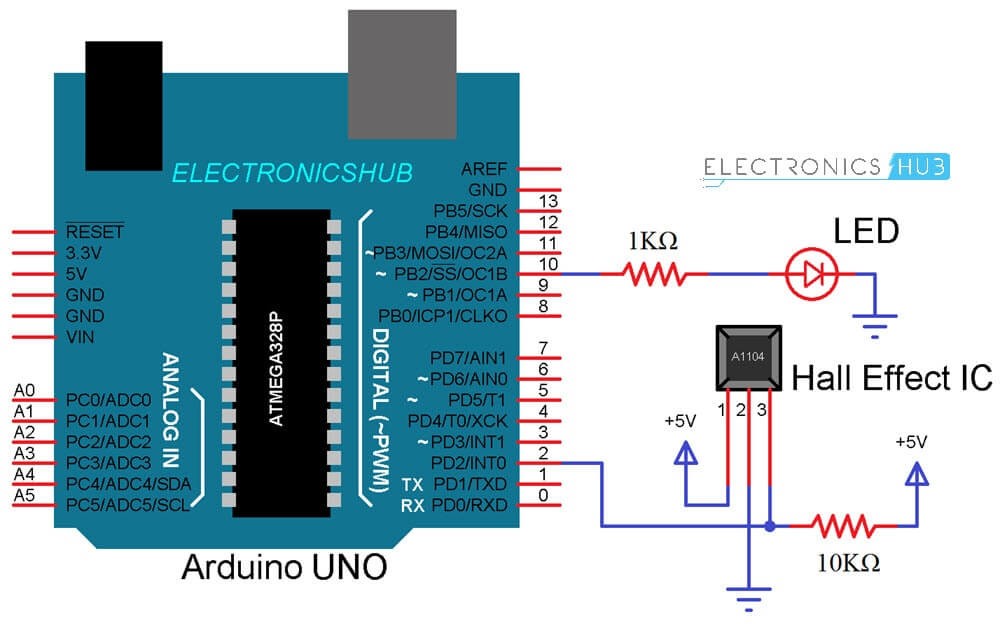
The image below shows the typical wiring of a US1881 to an arduino. The 10k resistor acts as a pull-up resistor to provide a stable input to the Arduino when there is no object being detected.
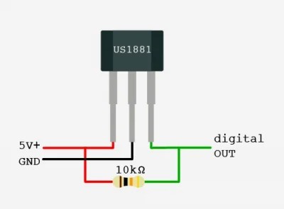
The output pin of the US1881 can be connected to any digital pin of the Arduino. If the sensor is used to measure the speed of a wheel, using a pin that supports external interrupts can be beneficial.
In this example, the hall sensor output is connected to pin 2 of the Arduino Uno.
| const int ledPin = 10; const int hallPin = 2; void setup() { pinMode(ledPin,OUTPUT); pinMode(hallPin,INPUT); } void loop() { if(digitalRead(hallPin) == LOW){ digitalWrite(ledPin, HIGH); } else { digitalWrite(ledPin, LOW); } } |
This Arduino constantly monitors the state of the Hall sensor’s output. When a magnet is placed near the sensor, it outputs a logic LOW signal.
The Arduino monitors this and if the signal is LOW, it turns on the LED. When there is no magnet present, the hall sensor’s output is logic HIGH. Observing this, the Arduino turns off the LED.
Conclusion
In this article, we discussed what Hall effect proximity sensors are, how they work, and their applications. Hall effect sensors are extremely useful in high speed applications like speed sensing.
Depending on the application, there can also be better alternatives like inductive, optical, or capacitive proximity sensors.

