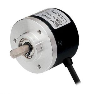
In industrial applications, sometimes it may require measuring the position or the speed of a rotating object like a wheel or a shaft/axle. Rotary encoder is an electromechanical device that can be used to obtain these measurements.
There are two types of rotary encoders: incremental rotary encoders and absolute rotary encoders. In this article, we’ll be looking at incremental rotary encoders, their working principle and applications.
What is an Incremental Rotary Encoder?
Incremental encoders belong to the family of rotary encoders. They are used to obtain information such as:
- Position
- Angle
- Rotational Speed
Incremental rotary encoders are found mainly in applications where the measurement of speed/angular velocity is required. This is done by counting the number of pulses per unit time generated by the encoder.
Unlike its sibling, the absolute rotary encoder, incremental encoders cannot provide information when the shaft is not rotating. They can only provide information about the motion of the shaft.
The pulses generated by the incremental rotary encoder must be calculated and processed elsewhere. This can be a microcontroller or a PLC (Programmable Logic Controller). Using the pulse count, the controller can then convert the information into information like position, speed and distance.
How Does an Incremental Rotary Encoder Work?
Incremental rotary encoders come in two configurations:
- Single channel incremental encoders
- Dual channel (Quadrature) encoders
Their functionalities are almost similar to each other. However, dual channel encoders allow us to detect the direction of rotation which a single channel encoder cannot.
The functional principle of an incremental rotary encoder is fairly straightforward. The sensor consists of a rotating, slotted disk attached to the shaft of it.
When the shaft is rotating, the disk also rotates as shown in the figure below. This is also known as a ‘codewheel’.
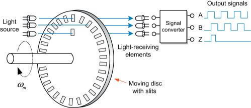
The slots in the wheel are used to generate ‘pulses’ each time a slot comes in alignment with the sensor. Incremental rotary encoders use technologies such as magnetic, optical, inductive, capacitive and laser to generate this pulse train.
The above diagram illustrates the operation of an optical incremental rotary encoder. A light source (LED) is placed across the disk and the receiving device (a photodiode/phototransistor) is placed in the line of sight.
When the disk rotates, the slots momentarily allow light to pass through. At this moment, the light beam reaches the receiver, and outputs a logic HIGH signal.
When the disk rotates further, the light beam is obstructed and the receiver does not receive the beam. This causes the output of that corresponding channel to go logic LOW.
Dual channel incremental rotary encoders have two of these channels named channel A and B.The slot placement for channel B are slightly offset from the slots for channel A.
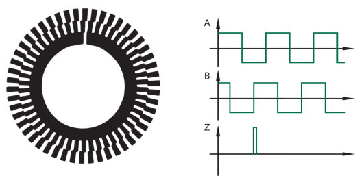
Sometimes, the sensor uses a single set of slots and the receivers are placed in an offset.
This special arrangement allows the outputs A and B to be ‘out of phase’.
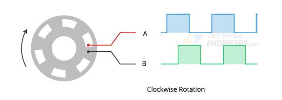
The microcontroller or the PLC can monitor both the channels to detect the rotational direction.
Depending on which channel (A or B) indicates a rising edge first, the direction can also be detected. Single channel encoders only have the channel A output and can only output a single pulse train.
For example, in the above diagram, a rising edge on A after a rising edge on B indicates that the wheel is rotating counter clockwise. Similarly, a rising edge on B after a rising edge on A indicates that the wheel/shaft is rotating clockwise.
On some sensors, there is a third channel called ‘Z’. Unlike the other two channels, there is usually only one slot for this channel. This is used to generate one pulse per revolution for tasks like homing and pulse count verification.
Incremental vs. Absolute Encoder
Incremental encoders can only work when the shaft is rotating.
Systems that use incremental rotary encoders must have a sophisticated program running to count the pulses the sensor is producing to determine the shaft position. They have an equally-spaced slotted disk acting as the codewheel.
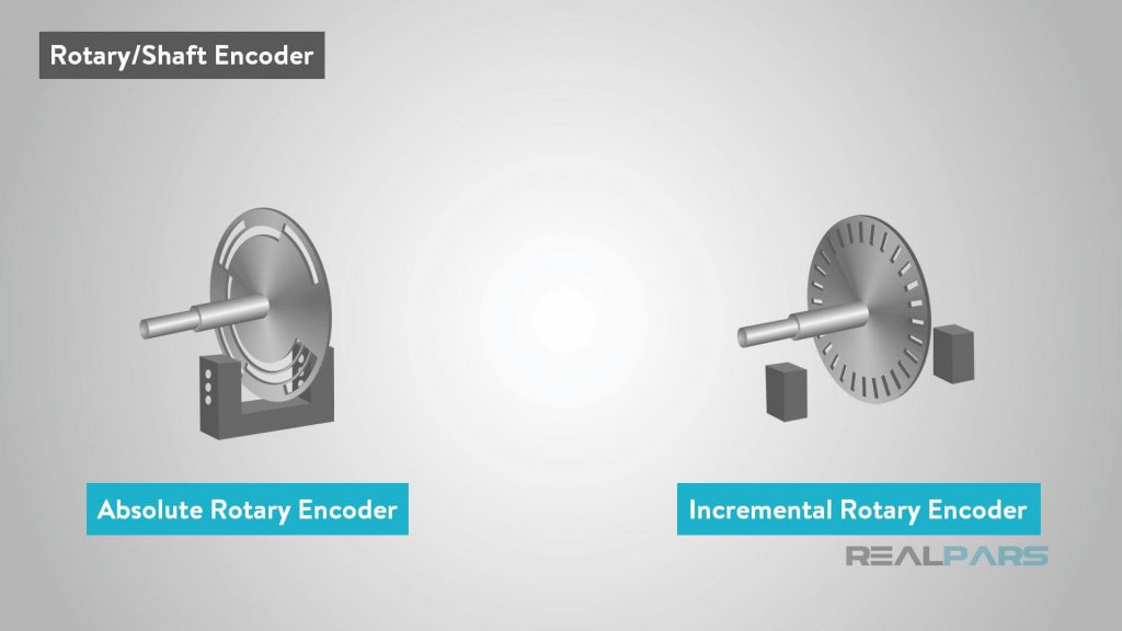
Absolute encoders have a specialized codewheel. This contains a non-uniform slot pattern, a unique code for each position of the shaft.
For any given shaft position, an absolute rotary encoder outputs a unique binary code that accurately describes the position. It also retains the output even when powered off since the codewheel itself contains the pattern.
Incremental encoders need to be powered on all the time to constantly generate the pulse train for velocity and distance calculations. However, absolute encoders can be powered on when necessary to obtain a reading.
Complexity wise, incremental encoders are simpler than their absolute counterparts. Therefore, incremental encoders are less expensive than absolute rotary encoders.
What are Incremental Encoders Used for?
Incremental rotary encoders find their applications from home appliances to automobiles to industrial automation applications.
One of the most popular applications for position sensing is the control knobs on electronic equipment such as car radio setups. The rotating knobs are infinitely adjustable, and only work when the device is powered on.
In the earlier days, the electromechanical computer mice also used these sensors to track the position along the two axes.
In industrial applications, incremental encoders are used to measure the speed of mechanical systems. This is particularly useful in motion control systems like material conveyors, robotic arms and CNC machines.
Incremental Encoder Specifications
When choosing an encoder for a particular application, there are multiple factors to consider.
- Outer diameter
- The outer diameter of the sensor housing (useful when mounting)
- Shaft type and diameter
- There are choices for the shaft type such as hollow shaft, half-hollow shaft, blind hollow shaft and through bore.
- The diameter must be within tolerances to be properly coupled with the object. 20mm, 25mm and 30mm shafts are available.
- Outlet way and cable length
- The position of the output cable connection. There are two configurations: side and out.Side configuration allows the connection of a detachable cable on the side. Cable out type has a fixed cable coming out of the rear of the sensor housing.
- For fixed cables, the sensors usually come equipped with a 2M black coloured cable.
- Supply voltage
- Indicates the maximum operating voltage of the sensor. There are options for %v (fixed), 5-12V, 12-24V and 24V(fixed) DC supplies.
- Output signal type
- A for single channel encoders, A and B for dual channel (quadrature) encoders and an optional Z for index pulse output
- Pulse count
- This parameter describes the pulses per revolution (PPR) and counter per revolution (CPR) values the sensor supports.
- Signal output method
- The type of output signal: voltage (V)/current(C) output, complementary(F) output or line drive(L, T) output
Incremental Encoder Electrical Characteristics
- Supply voltage
- Can vary from 5V to 24V
- Current consumption
- For voltage and current output types, the typical current consumption is less than 60mA. Driver types can consume up to 100mA.
- Output voltage (for voltage output type)
- HIGH level voltage: >= 3.5V
- LOW level voltage: <=0.5V
- Rise and Fall times
- Describes the time sensor takes to change the output from high to low(fall) or low to high(rise)
- Typical rise time for voltage output type: <= 500ns
- Typical fall time for voltage output type: <= 100ns
- Frequency response
- Maximum frequency the sensor can switch its outputs
- Typically falls below 300kHz
Incremental Rotary Encoder Circuit
As mentioned before, rotary encoders can be connected with either PLCs or microcontrollers to measure speed, position, distance and direction of rotation of a shaft. These devices need to be specially programmed to calculate these values and make decisions.
There are also specialized devices like counters and tachometers that can perform these calculations out-of-the-box and directly indicate the values. Let’s have a look at some of the circuits we can build using incremental rotary encoders:
Self-powered tachometer
Using the H7ER series self-powered tachometer by Omron, a single channel incremental encoder can be used to set up a tachometer that can display the RPM of a shaft.

The E6A2 is an AB type quadrature incremental encoder with NPN, open-collector outputs. Connecting it with the H7ER, the system acts as a tachometer which counts the frequency of the pulses to determine the RPM of the connected shaft.
High-speed up/down counter
The K3NC is a high-speed up/down counter with a variety of output modes. This device can be connected with an AB type rotary encoder to form an up/down counter according to the direction of rotation.
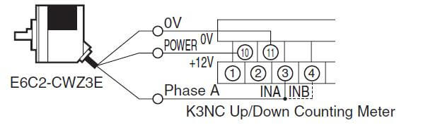
With this setup, the counting meter can be configured to output a signal to turn on/off a machine comparing the pulse count. It also supports communication with a PLC for process control applications.
Using these off-the-shelf components can eliminate the need for a complex device like a PLC where it’s not absolutely necessary. This is specially useful for smaller scale systems.
For the use in a PLC-based system, a HSC card (High Speed Counter) is recommended for high speed applications. The figure below shows the connection of a PNP open collector type incremental rotary encoder to a HSC input card coupled with a PLC.
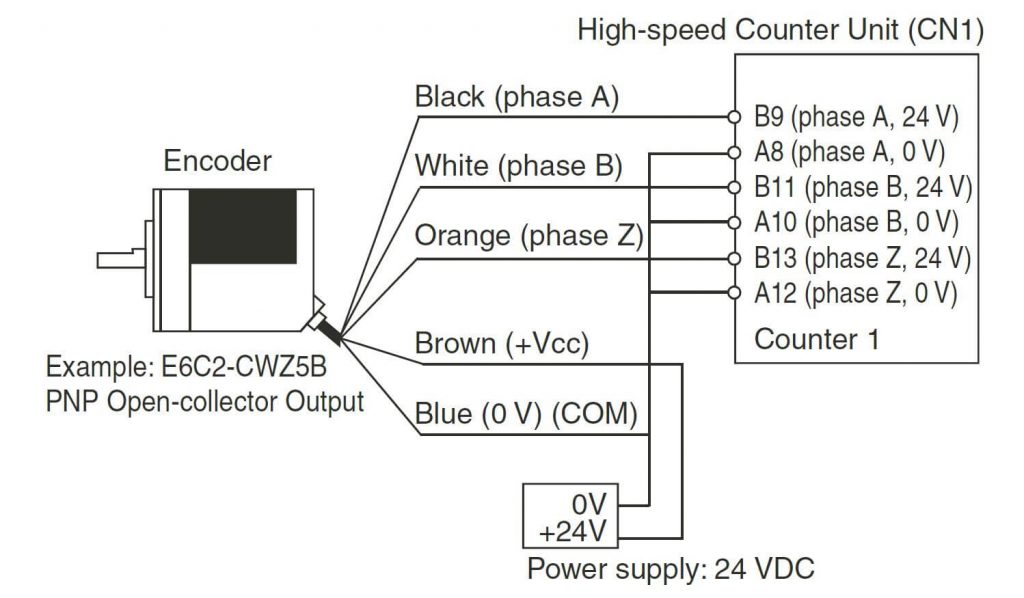
The sensor has A,B and Z outputs and they are connected to the HSC card as shown above. The counter card can be configured to send the counter reading the encoder shaft speed to the PLC. This setup reduces the processing overhead in the PLC program.
Incremental Rotary Encoder Arduino
In Arduino based circuits, rotary encoders are used as inputs to our programs.
We can use them to increase/decrease the value of a variable for tasks such as controlling the speed of a motor or the brightness of an LED. In more advanced applications, rotary encoders are used to navigate through menus as well.
The KY-040 is an off-the-shelf rotary encoder module available for Arduinos. It has the following pinout:
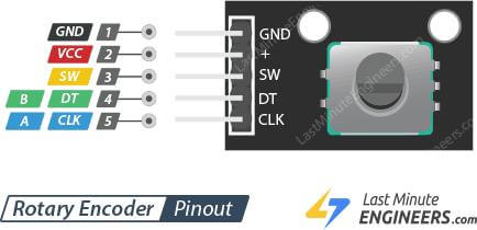
- GND – Ground connection
- VCC – 5V or 3.3V supply
- SW – push button switch output (0V when pressed, 5V when resting)
- DT – Data output
- CLK – Clock output
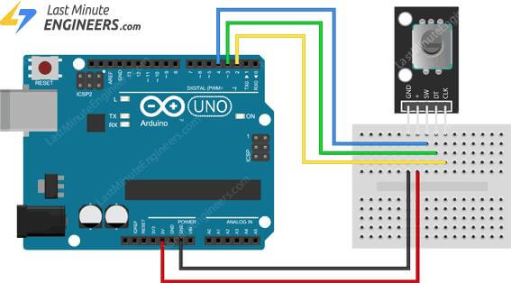
As an example circuit, let’s have a look at a test circuit where the encoder is connected to an Arduino UNO. The SW pin of the sensor is connected to pin 4, CLK to pin 2 and DT is connected to pin 3 of the Arduino.
VCC is connected to +5V and GND is connected to the GND pin of the Arduino development board as shown below.
Arduino Code for Rotary Encoder
This example code has been adapted from lastminuteengineers.com. It performs two main functions:
- Wait of CLK signal (pin 2) to change
- Observe if the button is pressed (pin 4 is LOW)
When the encoder knob is rotated, the program detects the change in CLK line. It then checks the state of the DT pin.
If both are the same, the encoder is being rotated in the clockwise direction and counterclockwise if otherwise. In the meantime, for each detection, the variable counter’s value is also increased/decreased depending on the direction.
The program also checks for the button state of the encoder. If it’s pressed, the program prints ‘button pressed’ onto the serial monitor. It also prints the current value of the number of pulses counted.
| // Rotary Encoder Inputs #define CLK 2 #define DT 3 #define SW 4int counter = 0; int currentStateCLK; int lastStateCLK; String currentDir =””; unsigned long lastButtonPress = 0;void setup() { // Set encoder pins as inputs // Setup Serial Monitor // Read the initial state of CLK void loop() { // Read the current state of CLK // If last and current state of CLK are different, then pulse occurred // If the DT state is different than the CLK state then Serial.print(“Direction: “); // Remember last CLK state // Read the button state //If we detect LOW signal, button is pressed // Remember last button press event // Put in a slight delay to help debounce the reading |
How to Check Incremental Encoder with Multimeter
To troubleshoot an encoder with a multimeter, it needs to be powered on. After powering on, set the multimeter to DC volts measurement mode, and connect the black probe with the GND wire of the sensor.
Slowly turn the shaft of the sensor while probing the A or B outputs of the sensor.
The voltage measurement should be fluctuating between close to 0V and VCC of the sensor. Note that the shaft needs to be rotating extremely slow to allow the multimeter to stabilize its reading.
If the voltage measurement is not changing, switch the multimeter to AC mode and repeat the same measurements. This time, turn the shaft faster. If the reading from the multimeter indicates a non-zero voltage, it can be concluded that the encoder is functional.
However, this is not a 100% accurate method of troubleshooting. Even though the multimeter displays a voltage reading, the sensor may still be malfunctioning. In this case, the sensor’s timing needs to be analyzed. For such tasks, an oscilloscope is required.
Conclusion
In this article, we discussed the operation, working principle and applications of incremental rotary encoders.
While incremental encoders are the most popular, absolute rotary encoders can be advantageous in certain instances. Select the most suitable sensor for your application by considering the characteristics we discussed in this article.
It will not only improve your system’s performance and reliability, but also will cut down any unnecessary costs involved.

