Introduction
Proximity sensors are used in industrial environments to detect the presence of objects. There are two main types of objects; metallic and non-metallic. Inductive proximity sensors are specially designed to detect metallic objects.
In this post, we’ll be having an in-depth look into inductive proximity sensors and their applications.
What is an Inductive Proximity Sensor?
Inductive sensors belong to the family of proximity sensors. They use the principle of electromagnetic induction to detect and measure objects. There are both digital and analog output sensors available in the market.
Inductive proximity sensors are non-contact type sensors. They can detect objects without physical contact. They find their application in detecting metallic objects in industrial automation environments. This includes objects made of iron, copper and aluminium.
Sensing range of inductive proximity sensors depends on the material type. Inductive proximity sensors work best with ferrous metal (iron objects), but we can use them to detect other metallic objects too.
Inductive Proximity Sensor Working Principle
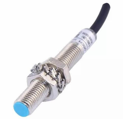
Inductive proximity sensors use the principle of electromagnetic induction to detect the presence/absence of metallic objects. These sensors look very similar to capacitive proximity sensors in terms of size. Shown below is the ALJ8A3-1-Z/N1 inductive proximity switch by OMCH.co
Let’s try to understand the working principle of inductive proximity sensors by starting with the method of detection, electromagnetic induction and Eddy currents.
Principle of Electromagnetic Induction
When a DC current is applied to a conductor (i.e. a wire), it creates a magnetic field around the conductor. This is called a ‘static magnetic field’ because it’s generated by a DC current.
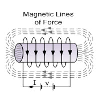
If the current source is an AC voltage, the magnetic field created starts to ‘oscillate’ back and forth.
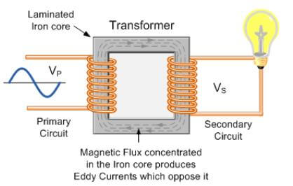
If a metallic object such as a piece of wire is placed within this magnetic field, this oscillating magnetic field causes an electric current to generate inside this second conductor. This principle is known as ‘electromagnetic induction’. This is the principle that can be found in electrical transformers as well.
This same phenomenon can also be observed when the magnetic field is static and the conductor moves through the magnetic field.
Eddy Currents
When a metallic object enters into an electromagnetic field, the field creates an electrical current inside the conductor according to the principle of electromagnetic induction. Sometimes this effect becomes undesirable. Eddy currents are the type of induced currents that start to circulate/loop inside the metallic object.
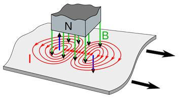
Eddy currents do not exit the object as electrical current flow. Eddy currents also disrupt the existing magnetic field. This is the phenomenon that inductive proximity sensors take advantage of to detect objects.
How does an Inductive Proximity Sensor Detect Metallic Objects?
Inductive proximity sensors use the same principle of Eddy currents to detect metallic objects. They measure the change in eddy currents induced in the object present, and output a signal accordingly.
Measuring Eddy currents in a closeby object however, is a complicated task. Therefore, inductive proximity sensors also have complicated circuitry inside them to process the signals and provide a decent output.
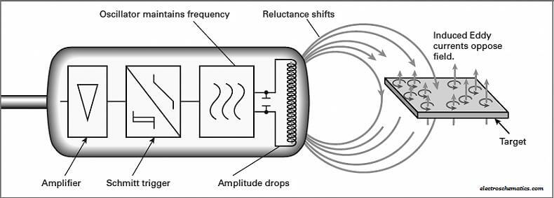
When activated, the sensor creates an oscillating magnetic field at the sensing face. This magnetic field is created using an LC oscillator, which consists of a capacitor and a coil.
A special circuit maintains the oscillation frequency at a constant. For AC sensors this frequency is about 10 to 20 Hz, while DC sensors work in the 500Hz to 5kHz range.
When a metallic object enters the generated magnetic field, the field induces an electrical current inside the object. This also causes Eddy currents to circulate inside the object.
As mentioned previously, the Eddy currents disrupt the magnetic field generated by the sensor.
This disruption damps the natural oscillation in the oscillator circuit. This is also known as ‘magnetic damping’. Magnetic damping increases the load on the oscillation. In turn, it reduces the amplitude of the oscillating signal.
A separate comparator circuit monitors this oscillating signal. Whenever the amplitude of the signal reaches below or above a certain threshold, the circuit activates the output. For a digital sensor, this is a logic HIGH or LOW output signal. For an analog sensor, the output signal is a current or voltage signal.
Build an Inductive Proximity Sensor Circuit
There are ready-made sensors available to purchase from various manufacturers. We can use them in any industrial automation application where metal detection is required. Similar to other sensor types, inductive proximity sensors also come in different output types: PNP and NPN.
There are also 2-wire inductive proximity sensors available.
Inductive Proximity Sensor Circuit using an Industrial Sensor
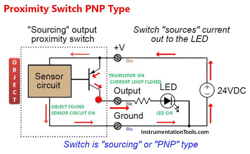
Let’s look at an example where a buzzer is activated when the sensor detects a metallic object. For this example, a PNP type inductive proximity sensor is used.
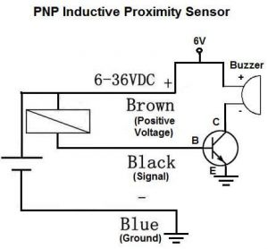
Following the typical wiring notation, the Brown wire of the sensor is its positive power supply terminal. The supply voltage can vary from 6V to 36VDV. The Blue wire is connected to ground.
The output of the sensor (Black wire) connects to the base of a general purpose NPN transistor. Since this is a PNP sensor, the output will be about 0V when no object is detected. When it detects an object, the output pin will output a voltage close to the supply voltage given to the Brown wire of the sensor.
Inductive sensors can output only a smaller amount of current. Therefore, connecting the output directly to a buzzer can damage the sensor. Using a transistor as a switch allows the sensor to output a voltage signal and control a high current load like the buzzer.
When the circuit is powered on and there is no metallic object present in front of it, the PNP inductive proximity sensor outputs LOW voltage (close to 0V). This reverse biases the transistor, which means that current does not flow through the buzzer. At this point, the buzzer is turned off.
When a metallic object comes into the detection range of the sensor, it outputs a logic HIGH signal. This signal turns on the NPN transistor. Since the transistor works as a switch, it now turns on the buzzer.
A Custom Built Inductive Proximity Sensor Circuit
Although inductive proximity sensors are commercially available, there might be an instance when you need to design a proximity sensor into a circuit board. This can be due to space limitations and unavailability of a suitable sized sensor.
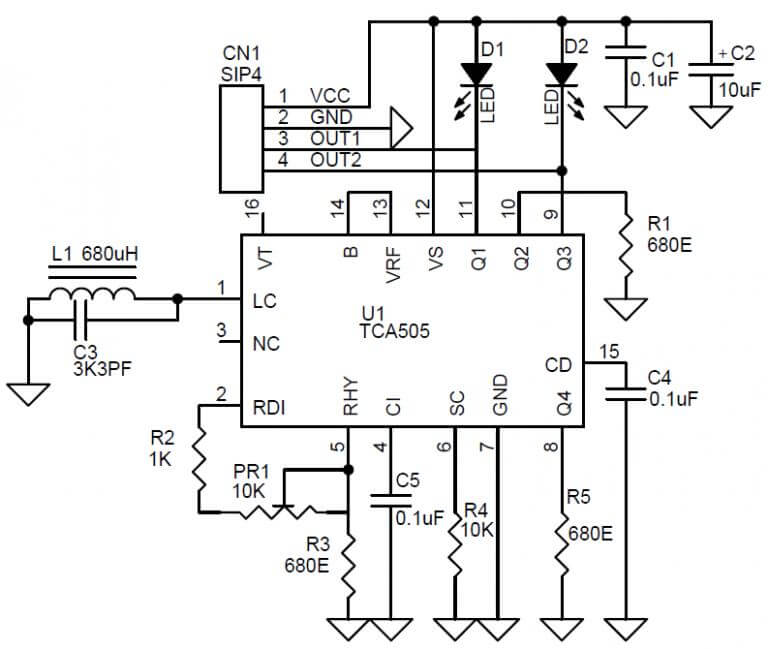
The TCA505 inductive proximity sensor switch IC by Infineon Technologies is a special purpose IC designed to be used in such applications. It has all the signal processing stages built into it, and require only a few external components to create a standalone inductive proximity switch.
Electronics-lab.com has an example application of the TCA505. The circuit shown here can detect metal objects within 5-10mm of distance from the PCB. The LC resonant circuit of this circuit is based on an open half-pot ferrite core.
This circuit can operate from 12V to 42V, and has two indicator LEDs, D1 and D2. D2 stays on when no object is present while D1 stays off. When an object is present, D1 lights up and D2 turns off. The sensitivity/sensing distance of the circuit can be controller using the PR1 potentiometer.
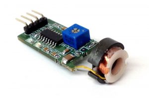
The image shown below is the final PCB designed by Electronics-lab.com.
Internal Circuits of an Inductive Proximity Sensor
Now that we know how an inductive proximity sensor works, let’s have a closer look at what makes them ‘tick’.
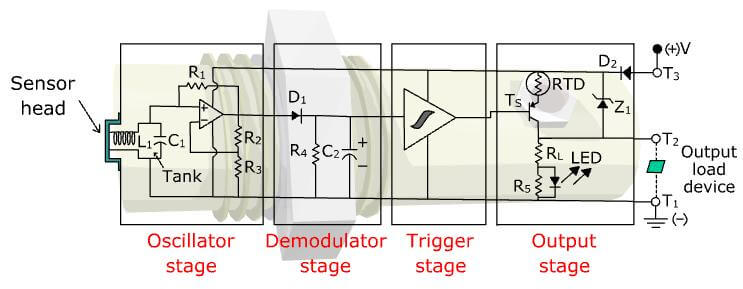
As we know now, an inductive proximity sensor has a complex circuitry inside its housing. The circuit has 4 main functional blocks. Namely,
- Oscillator Stage
- Demodulator Stage
- Trigger Stage
- Output Stage
Let’s discuss the functional block diagram of the inductive proximity sensor from sensing to output.
Oscillator Stage
The oscillator stage consists of the sensor head, which forms an LC tank circuit. This portion consists of a capacitor and an inductor, which is the sensing coil that generates the magnetic field. The op-amp helps to sustain the oscillation and keep the frequency constant. The signal output from oscillator stage resembles a sine wave.
Demodulator Stage
The output from the oscillator stage is connected to the demodulator stage. This stage accepts the sine wave produced, and rectifies it using a half bridge rectifier. The capacitor C2 further smoothens the voltage. Demodulator stage then feeds its output into the trigger stage.
Trigger Stage
The trigger stage consists of a special IC type called a ‘schmitt trigger’. Schmitt triggers have a special characteristic called ‘hysteresis’. For example, a schmitt trigger can set its output to HIGH when the input voltage is above 2.5V. But it will only set its output LOW back again when the input voltage falls below 2.0V.
Output Stage
The output stage is the final stage that controls the signal output of the sensor. This mainly consists of a transistor. The type of this transistor defines the sensor output type.
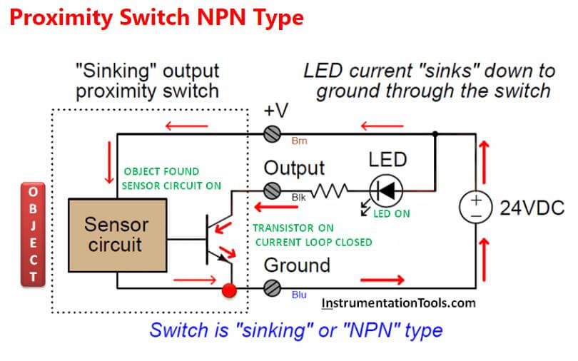
If the transistor is of NPN type, the sensor is called ‘NPN proximity sensor’. This particular sensor is a PNP type sensor that has a PNP transistor in its output stage.
The output is protected by an RTD (Resistance Temperature Detector), which protects the output stage if the Brown wire is short circuited with 0V. Diode D2 offers reverse polarity protection while R5 acts as a pull-down resistor for the output. D1 Zener diode protects the sensor from over-voltage.
Inductive Proximity Sensors vs Capacitive Proximity Sensors
Inductive and capacitive sensors are two of the most popular technologies among proximity sensors.
Inductive proximity sensors use the principle of electromagnetism and Eddy currents to detect metallic objects. When a metallic object comes closer to the sensor, the oscillation amplitude inside the sensor circuit gets damped. The rise or fall of the amplitude determines the output state of the sensor.
However, they cannot detect dielectric material such as plastic, wood or grain. This is sometimes an advantage because we can use inductive sensors to detect metallic objects inside a paper or plastic bag. For the most part, inductive sensors are used in machines to detect the position of moving parts.
Capacitive proximity sensors use the principle of capacitance to detect objects. Placing an object in front of the sensing face causes an oscillation to begin inside the sensor circuit. This is monitored by another subcircuit which controls the output.
These sensors can detect both metallic objects such as ferrous, aluminium and non-metallic objects like water, paper, glass and even powders. Capacitive sensors are used to monitor liquid levels, detect filled/empty status of containers such as bottles etc.
Inductive sensors have a relatively lower detection range (both distance and the field of view) than capacitive sensors. The operating distance of both the sensors depend on the material size, shape and composition.
Using Inductive Proximity sensors with Arduino
Sometimes, a DIY project may require detecting metal objects. Let’s have a look at how to use an inductive proximity sensor with an Arduino and how to get the readings from it. Mark Tutor have a very informative video on his channel on this.
The sensor used in this tutorial is the LJ12A3-4-Z/B NPN inductive proximity sensor. This sensor can work with 6-36VDC power supply. It has a detection range of 4mm and it can detect iron/steel alloys.
The sensor’s brown wire is attached to 6-36V power supply, and Blue wire is connected to 0V (ground). The pin 1 of the PC817 optocoupler is connected to the same 6-36VDC supply. The signal output of the sensor connects to PC817’s pin 2 through a 1k resistor. This resistor limits the current flow through the optocoupler.
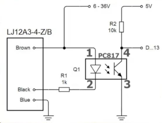
On the output side of the optocoupler, pin 4 is connected to 5V through a 10k resistor for current limiting. Pin 3 is connected to ground. The two grounds can be tied together, or can be left separated. Pin 4 is also connected to pin 13 of Arduino. This can be any digital/analog pin of the Arduino.
Functionality of the Circuit
When the circuit is powered on and no object is present, the NPN sensor outputs a logic HIGH signal. This means that the PC817 optocoupler does not function.
At this point, the transistor inside the optocoupler is not activated. Therefore, voltage at pin 4 is close to 5V. The Arduino sees this as a logic HIGH input.
When a metallic object is placed in front of the sensor, the sensor output connects to 0V. This causes the current to flow through the LED (pin 1 to pin 2 of the optocoupler), and turns on the optocoupler.
When activated, the transistor starts conducting current from pin 4 to pin 3. At this point, pin 4 of the optocoupler has a voltage close to 0V. The Arduino sees this as a logic LOW input.
Arduino Code Explanation
int limitSwitch = 13;
int state = LOW;
void setup() {
Serial.begin(9600);
pinMode(limitSwitch,INPUT);
}
void loop() {
int val = digitalRead(limitSwitch);
if( val != state ){
state = val;
Serial.print("Sensor value = ");
if( state == 0 )
Serial.println( "(0) Target Hit!" );
else
Serial.println( "(1) None");
}
}
The code begins with the pin definition and setting pin 13 as an input. Inside the loop function, the Arduino continuously checks the state of the pin 13. Whenever the pin 13 input transitions from HIGH to LOW or LOW to HIGH, the ‘if’ condition evaluates.
If the pin state is LOW (which means that there is an object present), it prints “(0) Target Hit!” onto the serial monitor. If the pin is HIGH, the Arduino prints “(1) None” onto the serial monitor.
This circuit can be easily changed to work with a PNP sensor by connecting the black wire of a PNP sensor to pin 1 of the optocoupler, and connecting pin 2 to ground though the 1k resistor.
Inductive Proximity sensor Price
The price of inductive proximity sensors primarily depend on their size, detection range and the output type. A typical sensor that has an operating voltage of 10-30V and a detection range of 8mm can cost you from $30 to $100+.
Sensors that have wires already attached tend to cost more as they are sealed and more resistant to dust and water.
AC inductive proximity sensors that have SPST contacts cost about $80 and are typically have an Ingress Protection (IP) rating of 67 or above.
Inductive proximity sensor symbol
The symbol for an inductive proximity sensor is as follows, as defined by the International Electrotechnical Commission (IEC). It consists of 4 main symbols that denote the nature of the sensor.
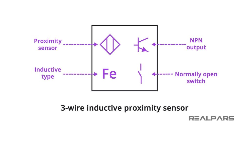
For all the inductive proximity sensors, the top left and bottom symbols are identical. Depending on the output type (PNP/NPN/SPST), the top right symbol can change.
The bottom right symbol indicates the normally open (NO) or normally close (NC) state of the sensor. This indicates whether the output signal is HIGH or LOW when an object is absent.
Engineershub.co explains all the wiring combinations (2-wire and 3-wire) for inductive proximity sensors, and provides illustrations for the two symbols.
Where are Inductive Proximity Sensors Used?
Inductive proximity sensors find most of their applications in industrial environments and heavy machineries. One of the most popular is the position sensing applications, where the sensors are used to detect the movement of machines such as forklifts and hydraulic actuators.
Contactless wheel speed sensing is also another application for inductive sensors. A wheel with slots/teeth is used to count the number of pulses the sensor reads per second to determine the rotational speed of the wheel. This is a common application in motor vehicles and conveyor belts.
Inductive Proximity Sensor Range
Unlike capacitive proximity sensors, inductive proximity sensors have a narrower sensing range.
However, they can detect objects within a range of 1mm to 60mm. Special purpose sensors can also be designed to have an increased sensing distance.
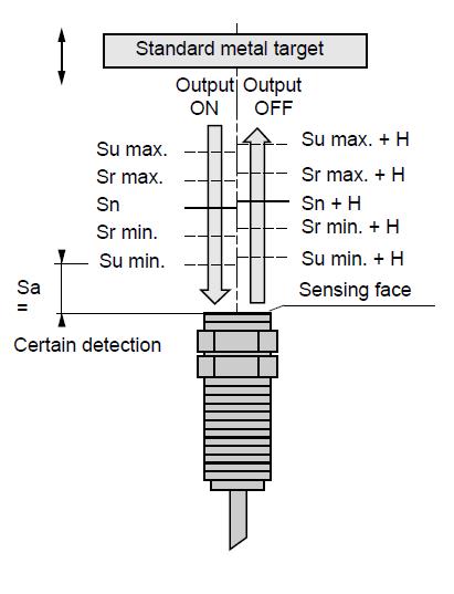
In this diagram, we can identify some of the parameters that are used to define the characteristics of the sensor. Sn is the nominal sensing distance. This is the distance that the sensor is designed to operate. This range does not take any variations into account.
Sr is the real sensing distance. This distance is defined at the rated voltage and the rated ambient temperature. Su is the usable sensing distance. Su defines the region where it is between 90% and 110% of the real sensing distance.
The most important parameter is Sa, the assured operating distance. This is between 0% and 81% of the nominal sensing distance, and the sensor is guaranteed to detect any detectable object within this region.
What are Inductive Sensors Made of?
The sensing face of an inductive sensor can be made of Ceramic or polyetheretherketone (PEEK). This is application dependent.
The housing of the sensor is based on various materials. It can be stainless steel, PPS, PBTB,nickel plated or teflon coated brass.
For applications where hygiene is key such as food processing, stainless steel complies with the standards. PPS is used to create housings where the sensor will be subjected to high temperatures. To resist abrasion and extreme heat and cold, PBTB is used.
How to Wire an Inductive Proximity Sensor
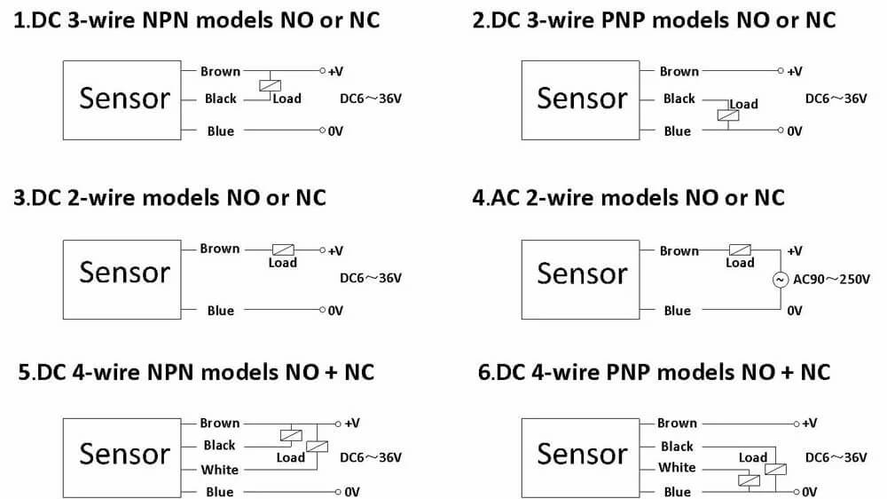
There are mainly 3 types of wiring schemes available. 4-wire sensors are not widely used, while 2 and 3 wire sensors are the most popular.
Here’s how sensors are classified according to their supply voltage and output types:
- AC or DC supply
- Determines whether the sensors works with 220V AC or 24V DC power supply
- Output type
- Transistor output (3-wire)
- Transistor output sensors can be either NPN or PNP. For both of those types, here are NO (Normally Open) and NC (Normally Closed) output options. Some sensors may even support both. (NO+NC).
- Relay output (2-wire or 3-wire)
- Transistor output (3-wire)
AC 2-wire and 3-wire sensors are always relay output type. DC sensors can be either relay or transistor output type. Relay output sensors also have NO, NC and NO+NC options.
Here is OMCH.co’s range of capacitive proximity sensors and the wiring options they provide:
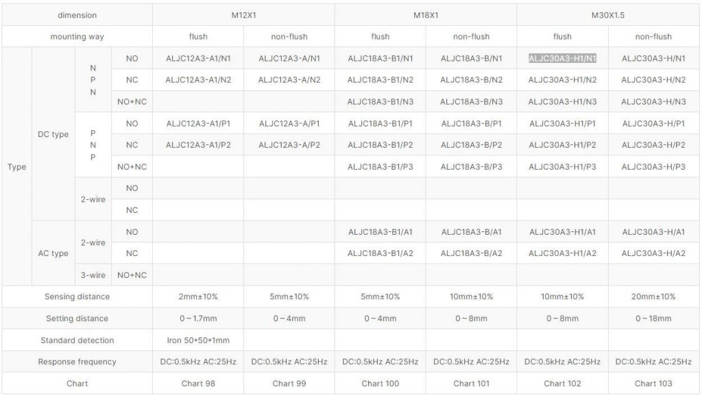
The following are the wiring diagrams used to wire proximity sensors to automation systems.
What Type of Material Does an Inductive Proximity Sensor Detect?
Inductive proximity sensors can detect the presence of only metallic targets. They cannot detect non-metallic objects such as ceramic, plastic, wood, paper and liquids.
However, they can ‘see through’ non-metallic objects to detect metallic objects. For example, inductive proximity sensors can detect metal objects behind an opaque plastic sheet.
How to Test an Inductive Proximity Switch
To test a PNP type inductive proximity sensor, the following circuit diagram can be used. When a metallic object is closer to the sensor surface, the attached LED lights up.
Similarly, the following circuit can be used to test a NPN type proximity sensor. For both the circuits, the series resistor with the LED should be around 2k to protect the LED.
What Materials Will Reduce an Inductive Proximity Switch range?
Inductive sensors work best with steel (Fe360). Using this as a reference, a special ‘correction factor’ is defined for other material types. The lower the correction factor, the lower the detection distance becomes.
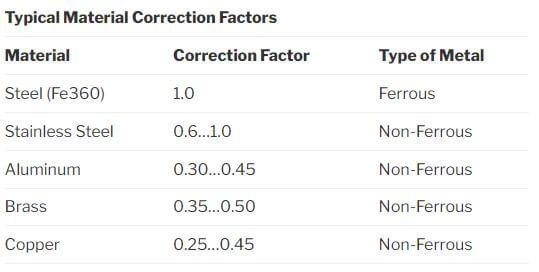
For example, if a particular proximity sensor can detect steel object at a 10mm distance, it would only be able to detect a brass object when it is approximately 10mm*0.25 to 10mm*0.45 (2.5mm – 4.5mm) close to the sensing surface.
How Accurate are Inductive Proximity Sensors?
During the manufacturing stage, inductive sensor designs undergo a thorough, precision calibration process. This involves laser guided tuning of the sensor resistors that determine the sensing distance and performance.
Even so, when a proximity sensor is deployed in the field, sometimes metallic dust or other particles can accumulate on the sensor surface over time. This reduces the sensitivity of the sensor over time.
Modern sensors come equipped with embedded microprocessors that can detect these particles, and adjust the sensor’s sensitivity accordingly. These sensor are hence called ‘chip immune’
Tips to Consider When Purchasing an Inductive Proximity Sensor
Before selecting an inductive proximity sensor as the option, it might be helpful to answer these questions:
- What type of objects do I need to detect?
- What is the relative sensing distance required?
- What’s the shape and size of the object I want to detect?
Depending on these factors, if
- The range is less than 80mm
- Only need to detect metallic (ferrous) objects
- The sensor should be resistant to harsh environmental conditions
- The sensor should work with high speed moving parts
an inductive proximity sensor might be a better choice. They are also relatively cheaper than other technologies such as capacitive or ultrasound sensors.
Will Inductive Proximity Sensors Work on Aluminum?
Normal inductive proximity sensors have a relatively hard time detecting objects made of aluminum. However, aluminum foil can be detected by inductive sensors due to a phenomenon called ‘skin effect’ that aluminum possesses.
If there’s a strict requirement to detect aluminum objects, there are ‘all-metal’ or nonferrous type’ that can detect all types of metal, including aluminum and copper.
Conclusion
In this article, we had an in-depth look into inductive proximity sensors, their construction, principle of operation and applications. These sensors make excellent metal detectors and find their applications in many industrial and non-industrial environments.
There are other types of proximity sensors such as capacitive, ultrasound, magnetic and photoelectric that may be more suitable for a specific. Follow this guide from DirectIndustry to learn more about choosing the right proximity sensor for your application.

