Introduction
The detection of presence or absence of an object from a distance is called ‘proximity sensing’. Magnetic sensors have a special place among the members of the proximity sensors family.
They are known for their supreme detection range when compared to their sibling, inductive proximity sensors.
This blog aims to discuss the overview of magnetic proximity sensors/switches and how they can be used in proximity sensing applications.
What is a Magnetic Proximity Switch?
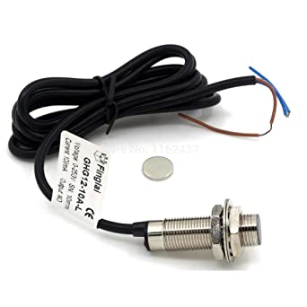
Magnetic proximity sensors/switches are non-contact position detection sensors. They detect objects using the magnetic property them. In other words, magnetic proximity sensors are specifically designed to work with magnets.
When it comes to detecting magnetic objects through non-magnetisable materials such as plastic, wood, or even aluminum, magnetic proximity sensors become extremely useful.
They are not only available in many size/package variants, but also have high mechanical stability in extreme shock/vibration conditions.
Magnetic Proximity Switch Working Principle
There are various technologies used in magnetic proximity sensors:
- Variable Reluctance
- Variable reluctance sensors are built using a permanent magnet and a pick-up coil wound around a ferromagnet. These sensors do not need an external power supply. When a magnet passes by the sensor, a voltage is induced in the coil and outputs the analog signal. There are ‘active’ variants of them that are powered which can provide more accurate sensing information such as zero-speed.
- Reed switches
- Reed switch-based magnetic sensors consist of a hermetically sealed glass bulb. The glass bulb encloses two ‘reeds’ that are magnetic. When a magnet is placed near the switch, the two reeds come into contact with each other, completing the circuit.

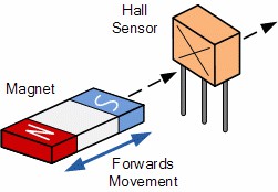
- Hall effect
- Hall effect sensors use the principle of the same name to measure the magnetic field generated by a magnetic object. There are two types of Hall sensors, digital and analog. Digital sensors output a logic HIGH or LOW signal. Analog sensors output a voltage/current proportional to the strength of the magnetic field.
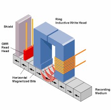
- GMR (Giant Magneto-Resistive Effect) Inductive
- GMR sensors consist of a wheatstone bridge circuit. Two of the resistors are specially designed to have internals that use ferromagnetic and non-ferromagnetic material. This makes the resistors’ resistance change when exposed to a magnetic field.
The wheatstone bridge circuit produces a voltage signal proportional to the magnetic field present. This voltage is passed through a signal conditioning stage into a comparator.
The comparator compares the signal with thresholds and switches the output stage to output the signal.
Magnetic Proximity Sensor Circuit Diagram
Magnetic sensors can be very useful, not only in industrial automation tasks but also in general-purpose switching tasks such as turning on/off an AC-powered appliance.
The following circuit is such an application where a magnetic reed switch is used to control a relay. Placing a magnet momentarily at the reed switch toggles the relay on/off.
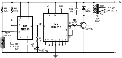
The circuit has three main blocks, the input circuitry, the time delay circuit, and the flip flop. Bringing a magnet close to the reed switch shorts the pin 2 of the NE555 timer to ground.
The NE555 is configured in monostable mode. In this configuration, when a 0V pulse is applied to pin 2, pin 3 goes HIGH for a certain amount of time and goes LOW (0V). The time constant is defined by the RC network formed by R2 and C1.
The output of the NE555 is connected to the clock pin (pin 3) of the CD4013 IC. This is a D-type flip-flop IC, and it is configured to be in ‘toggle mode’.
In toggle mode, everytime pulse is applied to pin 3, IC2 output transitions from HIGH to LOW or LOW to HIGH.
Pin 1 of IC2 is connected to the T1 transistor, which turns on/off the relay RL1. Since T1 is an NPN transistor, it turns on the relay when a positive voltage is given from IC2.
The relay has a freewheeling diode D1 to prevent damage to the transistor. This suppresses the inductive kickback when the relay turns off.
How to Test a Magnetic Proximity Switch
For a simple magnetic proximity switch like a reed switch, follow the circuit below to test the sensor.
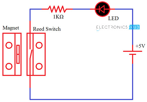
If the sensor is functioning properly, placing a magnet next to the sensor will turn on the LED.
If you have a multimeter, set it to continuity test mode or diode mode and connect the two leads to the two wires of the sensor. Bring a magnet close to the sensor and observe the reading of the multimeter.
The multimeter will beep or display a very small value close to zero if the sensor is working fine.
For sensors that have a built-in indicator LED, the first step is to power up the sensor using a voltage source. The voltage depends on the sensor model and can be 5V to 24VDC.
When the sensor is powered on, place a magnet in front of the sensor. If the LED on the sensor lights up, the sensor can be determined to be fault-free.
How to Connect a Magnetic Proximity switch
For a 3-wire proximity sensor, there are two configurations, NPN and PNP. PNP type requires a sinking type PLC while NPN type sensors need a sourcing type PLC. The figure below from RealPars indicates the typical, colour-coded wiring diagram for both sensor types.
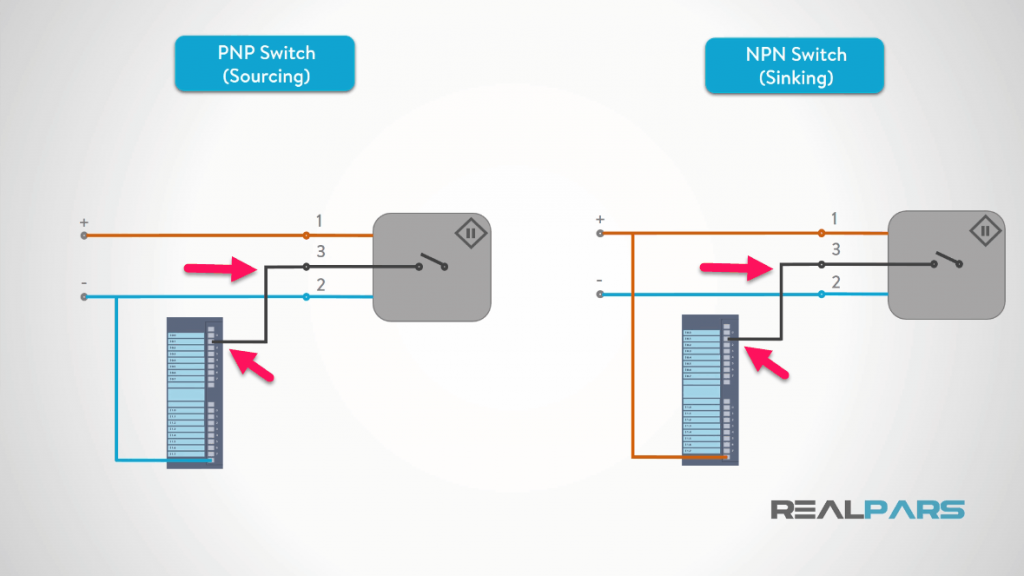
2-wire DC proximity sensors are relatively easier to wire. If the PLC is a sinking-type, a 2-wire PNP sensor should be selected. If the PLC is a sourcing-type, the sensor must be NPN output type.
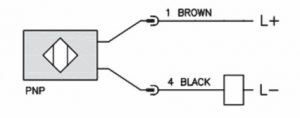
For a PNP sensor, connect the brown wire to +24V and black wire to the PLC input.
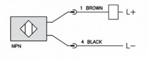
For an NPN type sensor, connect the brown wire to the PLC input and the Black wire to the 0V (common).
Magnetic Proximity Sensor Range
In general, magnetic proximity sensors’ range depends on the strength of the magnetic field. The typical sensing distance for a magnetic proximity sensor falls within the range of 0-80mm and can be slightly higher if the magnet is a very powerful one.
Conclusion
Magnetic proximity sensors are available in different technologies.
In this article, we went through the simple reed switch to the most complex GMR inductive sensors and discussed the functional principle behind them, how to test and use them in real-world applications.
Make sure to always research the options before selecting a particular sensor. This will ensure the optimum performance of your system.

