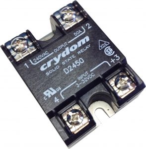
Solid State Relays (SSRs) are a substitute for electromagnetic switches such as relays. They have been introduced to mitigate the drawbacks that are inherent to general purpose contact relays (electromagnetic relays).
SSRs are available for both DC and AC systems.
Based on the output switching type, there are two major SSR types, zero crossing, and random crossing. In this article, let’s discuss the zero-crossing solid state relays to understand their operation and how to use them.
What is a zero-crossing Solid State Relay?
A zero-crossing SSR is an SSR to control an AC device that switches on when the load voltage is close or equal to zero. Like every other SSR, zero-crossing SSRs also do not have any mechanical contacts, and are purely built around semiconductor components.
Before we dive into further details, let’s discuss what zero-crossing means and why it is important for certain loads.
Importance of Zero-Crossing
In practical applications such as industrial environments, we come across two main types of loads: resistive and inductive. Equipment that have coils such as motors and transformers are inductive loads and devices such as heaters, incandescent light bulbs are resistive.
Since we’re switching an AC source, there is no guarantee at which point of the waveform the switch will turn on. Therefore the load voltage can be from 0V to 345V peak for a 230V system when powered on.
This timing can cause problems in the equipment being powered. For example, resistive loads such as heaters are preferred to be supplied with 0V and increased gradually to reduce the chances of damaging the heating element.
If not, the inrush current can burn the element. Since the voltage is AC, we only need to precisely control the point at which the switch turns on.
The point where the AC sinusoidal waveform is at 0V (where the waveform changes direction) is called the zero-crossing point. And this is the perfect time to switch on the device.
Zero-crossing SSR functionality
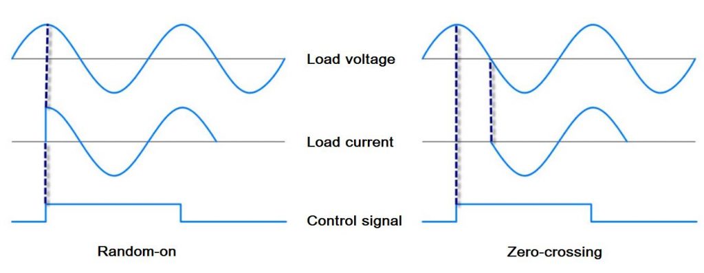
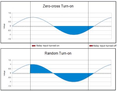
When the control signal is applied, the output is not immediately turned on.
Instead, it observes the waveform and waits for the current half-cycle to complete. When the current half-cycle is complete and the voltage reaches 0V (the zero-crossing point), the output is connected with the load.
This enables the load to follow the voltage waveform. If the load is an incandescent bulb, the gradual increase of the load voltage from 0V allows the filament to heat up and increase its resistance. This ensures a longer usable lifetime of the bulb.
What is the Difference Between Zero Cross and Random Cross?
When the control signal is applied, zero-crossing devices wait for the current half-cycle to complete before turning on the output. This always ensures that the load receives a clean sinusoidal waveform to work.
Random cross devices are turned on immediately. This can cause large in-rush currents to flow into the equipment and can cause damage to them. If the device being controlled is sensitive to high voltage spikes, random cross switching can damage them very easily.
Also, a zero cross device does not turn off immediately when the control signal is removed. Similar to turning on, they stay conductive until the current half-cycle is complete.
Zero-cross vs. Non-zero-cross Relays
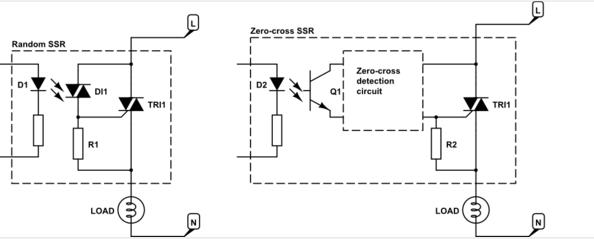
Apart from their primary difference in the switching timing, zero crossing, and non-zero crossing relays are nearly identical to each other. Zero cross relays have a few extra components in their circuitry to enable the zero-crossing detection.
Zero cross relays are more suitable for switching resistive circuits while random cross relays are the most suitable relays for controlling inductive loads such as motors and fans.
For advanced applications such as phase angle control/phase fired control, random cross relays are used due to their instant turn-on characteristics.
Zero-crossing SSRs also have very low switching losses. This allows the use of components with lower ratings which means that zero cross SSRs can be cheaper than random cross SSRs. To handle the high inrush currents and
Zero-crossing Solid State Relay Circuit
A typical 4-terminal zero crossing solid state relay circuit has the following circuit inside its housing. The schematic diagram below also shows a 600W load (a heating element) and a 120V source connected.
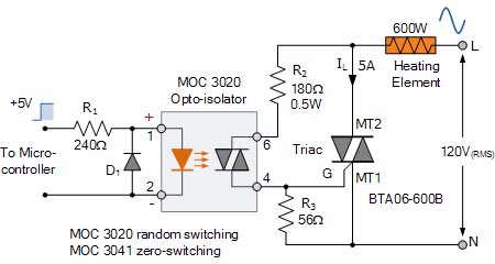
When the microcontroller sends logic HIGH to the SSR, the LED inside the opto-isolator is illuminated. The MOC3041 opto-isolator contains a built-in zero crossing detector. The LED turns on the zero crossing detector circuit.
The zero crossing circuit waits till the current half-cycle is complete. At the zero-crossing point, it sends a trigger signal to activate the photo triac inside the opto-isolator.
This causes the photo triac inside the to start conducting from pin 6 to pin 4. This pulse turns on the external, high power triac which then starts supplying current to the attached load.
The diode D1 protects reverse polarity damage to the relay. R3 resistor is in place to tie the gate pin of the trial to MT1 to ensure that the triac fully turns off.
Conclusion
In this article, we discussed zero-crossing solid state relays and their principle of operation. While they are superior than their contact relay counterparts, it should be mentioned that there are instances that traditional contact relays could be a better choice.
Therefore, analyzing the load type, max load voltage, expected average and surge current values will be certainly helpful in selecting a suitable SSR/relay for your application.

